ESP32

ESP32-WROOM-32 Breakout Board

Featured here is a breakout board for the Espressif Systems ESP32-WROOM modules incorporating a MCU with WiFi and Bluetooth connectivity. The board is designed to be minimalist and targeted towards battery operated devices. As such, no voltage regulator is included. For those not already familiar with the ESP32, this SoC offers the following features: Xtensa dual-core 32-bit LX6 microprocessor running up to 240MHz. 448KB rom for bootloader and core functions. 520KB SRAM (plus 16KB SRAM contained in RTC). 802.11b/g/n WiFi up to 150 Mbps. Bluetooth V4.2 BR/EDR and Bluetooth LE. 3.0 to 3.6V operation. A datasheet for the latest ESP32-WROOM-32E

ESP32

Espressif esp-idf & Eclipse IDE: Debugging with JTAG and OpenOCD

Developing ESP32 code by iteratively downloading code to your target via esptool can become laborious for anything but the smallest of projects. In addition to the UART Bootloader, the ESP32 can also be programmed and debugged via the JTAG interface. Debugging allows single stepping through your code, adding breakpoints and examining the contents of registers. Besides the rich debugging, programming over JTAG can also speed up development as the JTAG interface can be as fast as 20MHz as opposed to the serial download at a typical 460,800 bps. Setup This tutorial assumes you have Eclipse and the esp-idf set-up on

ESP32

Getting Started with the Espressif esp-idf & Eclipse IDE

The Espressif IoT Development Framework (esp-idf) is the official development platform for the ESP32 and ESP32-S series of SoCs from Fabless Semiconductor designer Espressif Systems. Espresif have developed the IDF eclipse plugin to make the setup and integration of the esp-idf with the eclipse IDE simple and relatively painless. Installation consists of four main steps: Install the Eclipse IDE Install the Espressif IDF Plugin for Eclipse Download and configure the esp-idf Install the esp-idf build tools Once installed, we run through the basics: Importing an IDF project Building Flashing SDK Config This tutorial will work you through setting up Eclipse

Electronics Hardware

Primer: The USB-C Connector

Anyone who has used a USB Type-A plug will know the fact that it takes three attempts to successfully insert. The USB Type-C connector sets out to solve this life’s little annoyance. But it doesn’t just stop there, it also offers many other advantages: Power Delivery USB has already established itself as an industry standard for low voltage (5V Type A) power and charging. Today everything from mobile phones, portable speakers to bike lights have a USB port for charging. USB ports can now be found integrated into power points, in cars, at bus shelters and even on trains. It

Embedded Linux

ANSI C Basic Lightweight NMEA Parser for GPS

For a recent OBD2 (vehicle/fleet data-logging) project running on a Raspberry PI Zero, I needed access to GPS data – both position/speed and time. The Raspberry PI doesn’t include a Real Time Clock (RTC). Upon boot, it doesn’t know what the actual time it is, unless it has access to a network and can retrieve the time via Network Time Protocol (NTP). With the logger fitted to a vehicle, a network connection wasn’t always available for NTP. Robust, feature rich software packages currently exist such as gpsd – a GPS service daemon. gpsd can also be used used in conjunction

CAN - Controller Area Network

SWCAN Single Wire CAN Transceiver Breakout Board

Single Wire CAN (SAE J2411) is commonly used in cost-sensitive Automotive applications where speed and cable length is not as onerous. It is also useful in applications were a traditional CAN differential pair is physically not possible. For example, on Type 2 Mennekes connectors used for Electric Vehicle (EV) charging, the communication between the supply equipment and the vehicle is performed via a PWM signal on a single Control Pilot (CP) pin in respect to earth. Tesla has used SWCAN to digitally communicate over this single pin. Various SWCAN drivers are available and generally share the same compatible pinout (SO8 and

CAN - Controller Area Network

Adding CAN to the BeagleBone (Black)

The CAN bus (Controller Area Network) was originally designed by Bosch for the automotive market to connect ECUs (Engine/Electronic Control Units) together. Today, this robust communications bus is commonly found, not only in vehicles, but also on the factory floor in automation (e.g. CANOpen) and other applications such as PV solar inverter/battery Energy Storage Systems (ESS). The Sitara AM335x MCU found on the BeagleBone includes two CAN 2.0 controllers (DCAN) using IP modules from Bosch. The BeagleBone Black PCB, however, doesn’t include any CAN bus transceivers and these must be added externally. CAN Transceiver Wiring The BeagleBone Black has two DCAN ports: DCAN0

CAN - Controller Area Network

Example C SocketCAN Code

Writing user space C code to talk to CAN devices via the Linux SocketCAN interface is relatively simple and efficient. SocketCAN uses the Berkeley socket API and hence is very similar to communicating with other network socket devices. Below is a simple guide to get you started reading, writing and filtering CAN packets. Official documentation for the SocketCAN interface can be found at: https://www.kernel.org/doc/Documentation/networking/can.txt Complete code for the following examples can be found at the following GitHub repository: https://github.com/craigpeacock/CAN-Examples These examples do not include make files. To build a source file, you can simply use gcc. For example, to build

CAN - Controller Area Network

Adding CAN to the Raspberry PI

The CAN bus (Controller Area Network) was originally designed by Bosch for the automotive market to connect ECUs (Engine/Electronic Control Units) together. Today, this robust communications bus is commonly found, not only in vehicles, but also on the factory floor in automation (e.g. CANOpen) and other applications such as PV solar inverter/battery Energy Storage Systems (ESS). The Raspberry PI doesn’t natively support CAN. The Broadcom SoCs (System on a Chip) used by the Raspberry PI doesn’t include a CAN controller. The Linux kernel supports CAN and includes SocketCAN drivers for the Microchip MCP2515 Stand-alone CAN Controller with SPI Interface. Various

Electronics Hardware

LT8490 MPPT Buck-Boost Multi-Chemistry Battery Charger

Most PV solar regulators are buck (step down) regulators and require the PV panel voltage to be above the battery voltage. This design uses a buck-boost topology and allows the PV solar voltage to be above, below or equal to the battery voltage. For example, you could charge a 48V battery bank from a 72 cell PV panel with a maximum power point voltage (VMP) of around 37V. The LT8490 allows for a PV panel voltage in the range of 6V to 80V. This makes it ideal for commodity 72 cell PV panels that typically have an open-circuit voltage (VOC)

Electronics Hardware

Review: Li-ion LiPo LiFePO4 Lithium Battery Active Equalizer Balancer Energy Transfer Board

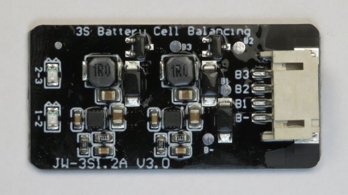
Cheap Lithium Battery “Active Balancer” boards have been turning up on Aliexpress and other eCommerce sites. But there has been some scepticism if they are genuinely active balancing and quite a few conflicting forum posts. Some have even claimed the ‘1R0’ inductors are actually 1 ohm resistors. The more traditional passive balancer boards will simply dump any excessive charge into a resistor, wasting this energy. For example, if the maximum voltage threshold was set at 4.2V, once the cell’s terminal voltage exceeded 4.2V, any excess charge would be dumped into a resistor and dissipated as heat until the terminal voltage

Electronics Hardware

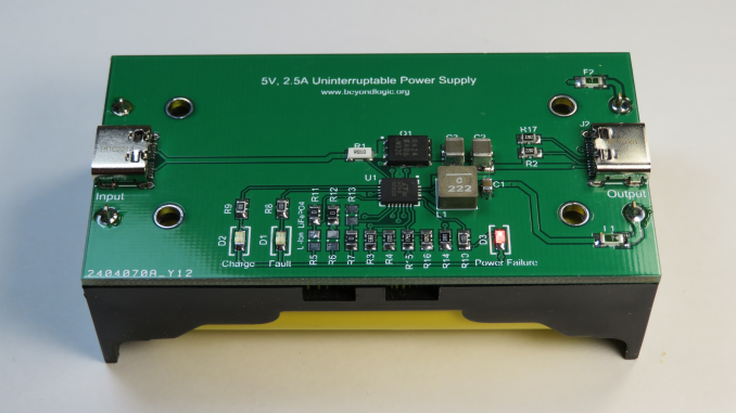
LTC4040 5V, 2.5A Uninterruptible Power Supply (UPS) with USB-C

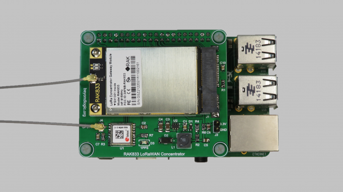
Motivation I have had the requirement to back-up small 5V low-powered devices such as a Foscam C1 security camera and a Raspberry PI based LoRaWAN concentrator. Many commonly available 5V Uninterruptible Power Supplies feature a two chip design with a Li-Ion battery charger to charge the back-up battery, and boost converter to step up the battery voltage back up to 5V. Like most of my personal designs, cost was not a primary driver. I was on the search for a elegant, preferably single chip device that was fit for purpose. Lithium Ion batteries can be stressed when left at full

Electronics Hardware

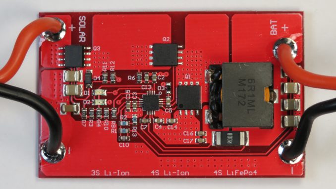
Review: BQ24650 5A MPPT Solar Controller 3S / 4S Li-Ion, LiFePO4, 12V Lead Acid

Designs based on the Texas Instrument’s bq24650 Synchronous Switch-Mode Battery Charge Controller for Solar Power With Maximum Power Point Tracking are commonplace on Aliexpress, ebay and Amazon. Consumers can purchase assembled PCBs, such as the one pictured above, or complete product enclosed in a relatively nice aluminium extruded housing. According to the silkscreen of versions pictured on-line, different variants are available including: 3S Li-Ion 4S Li-Ion 4S LiFePo4 12V Lead Acid I’m still old-school and wanted to purchase a 12V lead acid version, but couldn’t find any available for sale. And like many similar electronics products from the above mentioned

Software

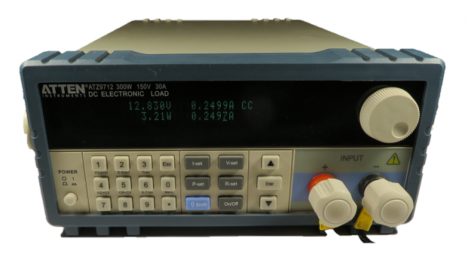
ATZ97 / M97 Series Programmable DC Load Modbus Interface Software

The Atten ATZ97 / Maynuo M97 Series programmable DC loads has a RS-232 port that can be used for instrument control and acquisition. Rather than using more conventional text based SCPI (Standard Commands for Programmable Instruments) commands, these instruments use Modbus, a protocol designed for PLCs (Programmable Logic Controllers). The M97 series loads come bundled with “M9700 Load Monitor Software” that does a reasonable job in controlling the DC load and recording data. However, I wanted to use the DC load in a test setup with a DC Power Supply to plot the efficiency of DC-DC converters. To accomplish this

Electronics Hardware

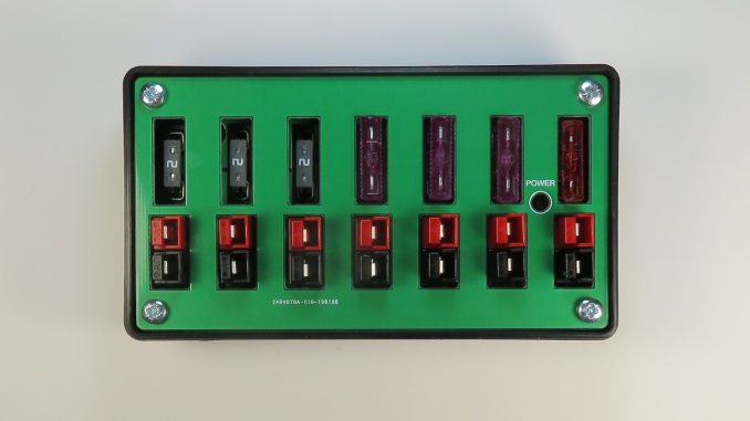
Powerpole Distribution Box

For far too long, I have been on the search for the ideal way to distribute power for low voltage systems, typically 12V. I have an small assortment of domestic networking gear, small embedded systems, LED desk lamps, battery chargers and USB chargers that operate from a backed-up 12V PV solar supply. I have finally settled on the “Powerpole” 15-45 connector from Anderson Power Products. The 15-45 denotes that the connector comes with terminals rated from 15 to 45 Amp. The housings are designed for voltages well exceeding 100V AC or DC depending upon your choice of UL or IEC certification.

Electronics Hardware

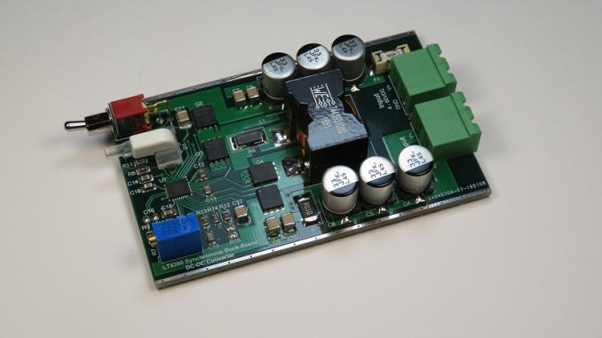
LT8390 Synchronous Buck-Boost DC-DC Converter

For the past couple of years, I have been powering my Sony 55” LCD TV and charging a couple of laptop computers from a 12V solar system. Both the Sony TV and the laptop computers have an input voltage of 19.5VDC. To step up the voltage from the battery, I purchased two “LTC3780 Automatic lifting pressure constant voltage step up step down 10A 130W” a.k.a. LTC3780 – High Efficiency, Synchronous, 4-Switch Buck-Boost DC-DC Converters from ebay. These boards operated from a moderately wide 5 – 36V input and had an output voltage range of 1 – 30V. The LTC3780 has

Electronics Hardware

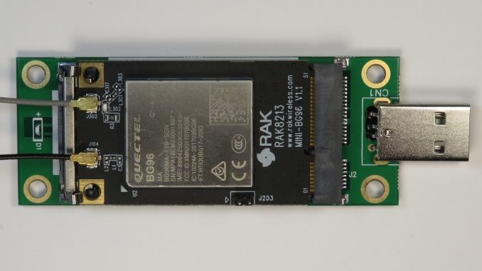
Review: RAK8213 LTE Cat M1/NB1 IoT Modem

The RakWireless RAK8213 is a Quectel BG96 based 4G LTE Cat M1/Cat NB1/EGPRS modem in a PCI Express MiniCard Form Factor. LTE categories M1/NB1 combined with innovations including Power Saving Mode (PSM) and Extended Discontinuous Reception (eDRX) can rival power consumption and battery life of other IoT Technologies such as LoRa and Sigfox. The RAK8213 is available from Aliexpress for just $39.90 USD. The BG96 includes an integrated TCP/IP stack with HTTP and MQTT client, greatly simplifying firmware development. The RAK8213 features: LTE Cat M1, Cat NB1 (NB-IoT) and EGPRS. GNSS – Support for GPS, GLONASS, BeiDou/Compass, Galileo and QZSS. Ultra Low Power.

Embedded Linux

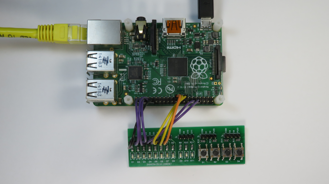
An Introduction to chardev GPIO and Libgpiod on the Raspberry PI

Linux 4.8 introduced a new GPIO user space subsystem for accessing GPIO. This tutorial provides an introduction to the new Character Device GPIO and explores how to control GPIO from the command line. sysfs GPIO User-mode GPIO (General Purpose Input/Output) has historically been performed via the legacy “integer-based”sysfs pseudo file system.  For example, to set GPIO25, one would: # echo out > /sys/class/gpio/gpio25/direction # echo 1 > /sys/class/gpio/gpio25/value GPIO access via this legacy sysfs interface has been deprecated since version 4.8 of the Linux kernel. chardev GPIO The new way of doing GPIO is via the “descriptor-based” character device ABI (Application Binary

Electronics Hardware

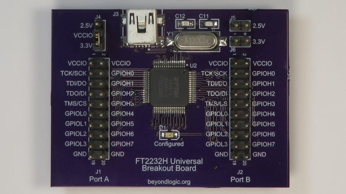
FTDI FT2232H USB to UART/MPSSE/JTAG Breakout Board

The FTDI FT2232H Hi-Speed Dual USB UART/FIFO Breakout Board provides a variety of standard serial and parallel interfaces: Asynchronous UART JTAG I2C SPI Parallel FIFO The board includes two linear regulators offering either 3.3V or 2.5V IO. An on-board Serial EEPROM stores custom USB descriptors, VID/PIDs and configurations. Design Files Design files can be downloaded from the Circuit Maker website. Circuit Maker is a free EDA tool from Altium. FT2232H Breakout version 1.A.1 Gerbers (Zip) FT2232H Breakout version 1.A.1 Schematics (PDF) The PCB for this design was fabricated by oshpark.com

Embedded Linux

Compiling U-Boot with Device Tree Support for the Raspberry Pi

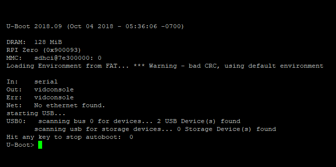
U-Boot U-Boot (The Universal Bootloader) is a popular, feature rich, open source bootloader for embedded systems. It is licenced under the GNU General Public Licence version 2. While its primary purpose is to boot an operating system, such as Linux, it also provides many useful tools for developing and debugging embedded systems. This includes support for many common file-systems including FAT, ext3, ext4, NFS etc and interfaces such as USB, Ethernet (IP), MMC and even Asynchronous Serial (Kermit/xmodem/ymodem). This allows the developer to load new images and file-systems from a variety of sources for testing and/or reflashing. It also includes