

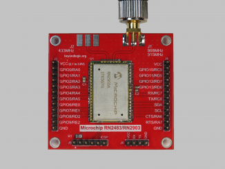
The RN2903 Wireless LoRa Module from Microchip ships with an on-board LoRaWAN Class A protocol stack. This stack can be accessed via ASCII based commands over a UART interface. For many, this is the interface of choice, offloading the complexity of the LoRaWAN stack to a dedicated processor contained within the module. Another advantage is Microchip can fully certify the module and stack.
I decided not to use the on-board stack for two reasons:
- Here in Australia, we must use the AU915 frequency plan. Microchip has beta firmware for this frequency plan, but it is not yet publicly available. Developers must contact the local Microchip FAE to obtain a copy.
- I didn’t want to have two microprocessors. I had just spun a breakout board for the RN2903, and included I/O labels for the on-board PIC18LF46K22 microcontroller pins. I wanted to find out just how easy it is to target the internal PIC microcontroller and if I can hang sensors directly off the module.
Using the LoRaWAN™ Library Plug-in for MPLAB® Code Configurator
Microchip have done a great job documenting how to run the LoRaWAN Library on the RN2xx3 modules, detailing the step by step MCC (MPLAB Code Configurator) configuration in Chapter 3 of the LoRaWAN Library Plug-in for MPLAB Code Configurator User’s Guide.
I started out by following these instructions. This showed how to create a new project and configure the LoRaWAN stack, the TMR1 base timer, MSSP2, external interrupts and system clock/resources.
At the time of writing, I used the LoRaWAN Library v01.10.00_beta. It is yet to include support for the AU915 Frequency Plan, but the North America NA915 Plan is very similar, except for the base frequency. To proceed with the generation of the stack, I selected North America as the ISM Band, but with the plan to hack the frequency defines once the stack had been generated. By default, all 72 LoRa upstream channels were enabled. I wanted to target The Things Network in Australia, who use Sub Band 2. I switched off all channels except for channels 8 to 15.
AES Encryption
The LoRaWAN stack uses AES-128 encryption. According to the Microchip documentation (Chapter 5.5 LoRaWAN Stack Encryption), Microchip are unable to distribute the AES.C and AES.h files due to different licencing schemes.
Follow the instructions in Chapter 5.5, download the SW300052 Data Encryption Libraries, extract to the correct location and remove the “rom” keywords to ensure compatibility with the XC8 Compiler.
At this stage, you should be able to successfully build and link the project.
EUSART/printf
The next step was to get the UART working, so we can print debug messages. Using MCC, I added the EUSART1 peripheral with a baud rate of 9600bps and redirected STDIO to USART.

I then added the following test code to main() function, and built the project.
printf("\r\n");
__delay_ms(1000);
printf("\r\nRN2903 Test Program\r\n");
Downloading to the target, successfully yielded a “RN2903 Test Program” in putty, my preferred Terminal program.
AU915 Hack
To support the AU915 Frequency Plan, I proceeded to hack the frequency definitions in mcc_generated_files/LoRaWAN/lorawan_defs.h. You can skip over this section if you are in North America or Europe.
I added two new definitions:
#define FREQ_915200KHZ                          915200000
#define FREQ_915900KHZ                          915900000
and then replaced the following block:
#define NA915_UPSTREAM_CH0                      (FREQ_902300KHZ)
#define NA915_UPSTREAM_CH64                     (FREQ_903000KHZ)
#define NA915_DOWNSTREAM_CH0                    (FREQ_923300KHZ)
with:
#define NA915_UPSTREAM_CH0                      (FREQ_915200KHZ)
#define NA915_UPSTREAM_CH64                     (FREQ_915900KHZ)
#define NA915_DOWNSTREAM_CH0                    (FREQ_923300KHZ)
Before using the LoRa stack, I wanted to verify the following hack was enabling the correct channels. I added the following code to main() function and proceeded to downloaded it to the target.
LORAWAN_Reset();
LORAWAN_Init(RxData, RxJoinResponse);

// Print list of enabled channels
for (int ch = 0; ch <= 71; ch++) {
  enable = LORAWAN_GetChannelIdStatus(ch);
  freq = LORAWAN_GetFrequency(ch);
  if (enable) printf("Channel %02d Enabled: %ldHz\r\n",ch, freq);
}
It printed the following strings, verifying that channels 8 to 15 (Sub Band 2) were enabled, and using the expected frequencies for AU915:
RN2903 Test Program
Channel 08 Enabled: 916800000Hz
Channel 09 Enabled: 917000000Hz
Channel 10 Enabled: 917200000Hz
Channel 11 Enabled: 917400000Hz
Channel 12 Enabled: 917600000Hz
Channel 13 Enabled: 917800000Hz
Channel 14 Enabled: 918000000Hz
Channel 15 Enabled: 918200000Hz
Over the Air Activation (OTAA)
The next stage is to register the device with The Things Network. There are two methods to do this, Over-the-Air Activation (OTAA) or Activation by Personalization (ABP).
The Microchip LoRaWAN Library will support both methods. Over-the-Air Activation (OTAA) is the preferred and most secure way to connect. Obtain the relevant keys from your Things Network console and add them to your main source file:
// OTAA Keys:
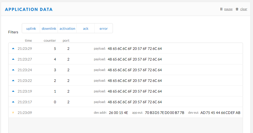
uint8_t applicationEuiNew[8] = { 0x70, 0xB3, 0xD5, 0x7E, 0xD0, 0x00, 0xB7, 0x7B };
uint8_t deviceEuiNew[8] = { 0xAD, 0x75, 0x45, 0x44, 0x66, 0xCD, 0xEF, 0xAB };
uint8_t applicationKeyNew[16] = { 0xD7, 0xA0, 0xE5, 0xB6, 0xA0, 0x75, 0xB4, 0x2A, 0xC9, 0xDF, 0x8F, 0xD5, 0x00, 0x08, 0xA7, 0x89 };
Next we must load the keys in and perform an OTAA join. Once joined, the demo code uses the LORAWAN_Send() function to send the LoRaWAN application the “Hello World” string.
LORAWAN_SetApplicationEui(applicationEuiNew);
LORAWAN_SetDeviceEui(deviceEuiNew);
LORAWAN_SetApplicationKey(applicationKeyNew);
LORAWAN_Join(OTAA);

while (1)
{
    LORAWAN_Mainloop();
    // All other function calls of the user-defined
    // application must be made here
    LORAWAN_Send(UNCNF, 2, "Hello World", 11);
}
Start the above code running on your target RN2903 LoRa module and open an Application Data window in the Things Network Console. You should see the initial activation, followed by a series of Uplink packets containing the “Hello World” payload.
Source Code
The source code for this project can be obtained from https://github.com/craigpeacock/RN2903-Demo

Thanks for your post
With your example was possible send messages to my gateway.
But I need a help, I don’t understand what is the command for get the receive RX data from gateway
Hi! I’ve the same doubt! Have you ever solved it? If yes, can you say me how?
Hello. I’ve been playing around with your example and I must say it’s working wonders. Now… I would like to reduce the rate in which the uC queues tx messages… as you may know 1s intervals are overkill in LoRa. What should I look after?
Hi! I’ve the same doubt! Have you ever solved it? If yes, can you say me how?
Hi,
I use Lora mote 2903 with a different microcontroller. So i find it difficult in extablishing a connection. Can you say how to configure lora gpios to communicate with sx1276 transceiver. Any help would be greatly appreciated.