

The Huawei R4850G2 is a very capable 48V Telecommunications grade power supply available brand-new at cheap surplus prices (normally under $100 USD). Rated at 3000W, it can deliver a considerable 56.1A when powered from a suitable 200-240V rated AC source. The CAN2.0B interface allows for online monitoring and/or adjustment of the output voltage and current.
Given the power supply is a Telecoms spare part (most likely for a Huawei mobile phone Base Terminal Station), a surprisable amount of official documentation exists on the hardware from the manufacturer:
But when it comes to the CAN communications protocol and operation, the best source of information, although sketchy, comes from radio/electronics enthusiasts in Chinese forums.
We strive to demystify some of the details below and provide reference software to talk to the unit via CAN.
The Purchase
I was first made aware of the R4850G2 by YouTuber Schematix. He presented a 17 minute video on the power supply at Cheap 3Kw PSU for Induction Heater ll Huawei R4850G2 PSU
My PSU was purchased from a local Australian ebay merchant (link here) for $49 AUD plus $15.35 shipping (Approximately $50 USD). However, if shipping from Australia is cost prohibitive, Aliexpress and Alibaba appear to also be a good source.
While Schematix details modifying the supply to make good connection to the edge connector, you can pick up a suitable connector: i.e. For Huawei R4850G2 rectifier module communication power plug. This set me back $23.28 AUD, but allows for a more professional connection.
Connections
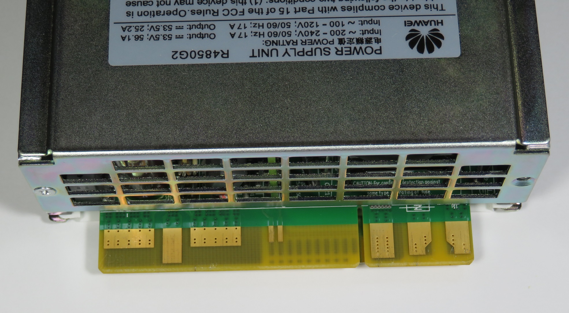
The power supply is designed to be inserted into a slot/backplane and hence all connections to the power supply is by means of a edge connector. Inclusion of Pre-charge pins allow multiple units to be paralleled and hot swapped.
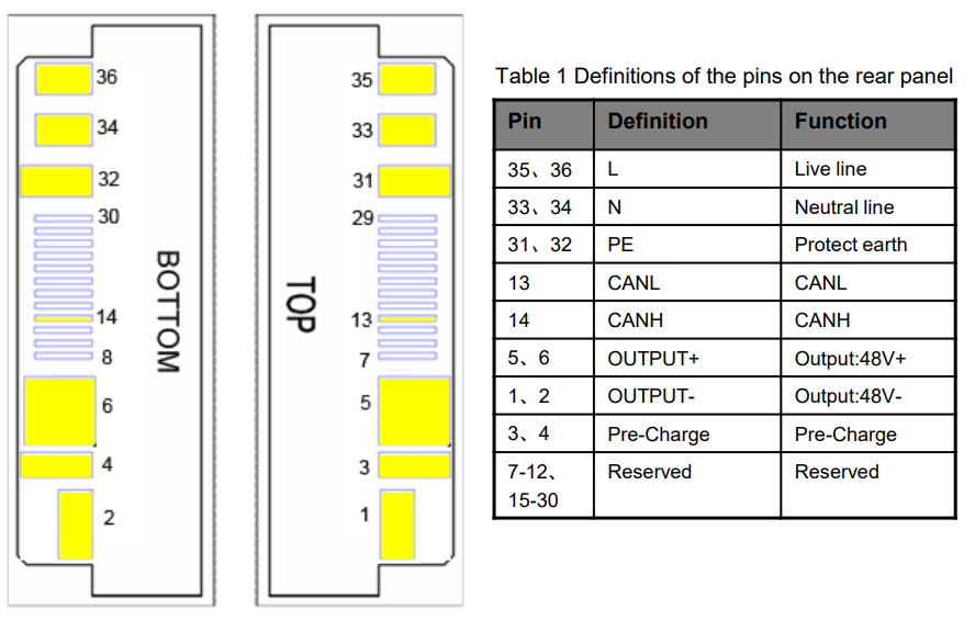
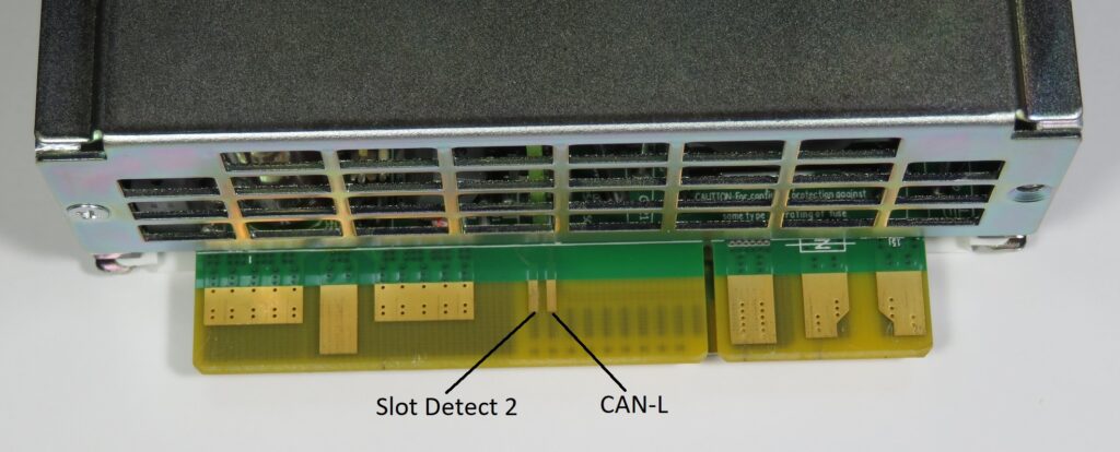
Huawei go someway in documenting the connector in version 1.4 of their User Manual. However, they miss off two critical pins required to enable an output. Next to the CAN pins are what we call ‘slot detect 1’ and ‘slot detect 2’
Mating Connector
As indicated earlier, I had also purchased a mating connector for the PSU from ebay. Below are the pictures on arrival.
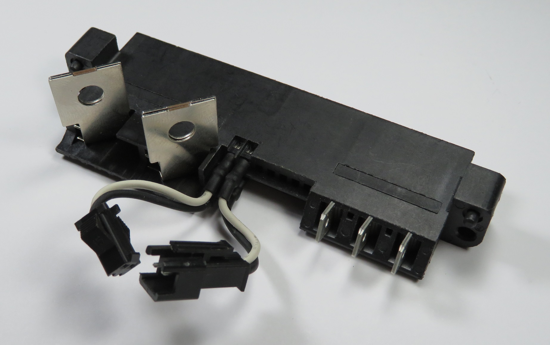
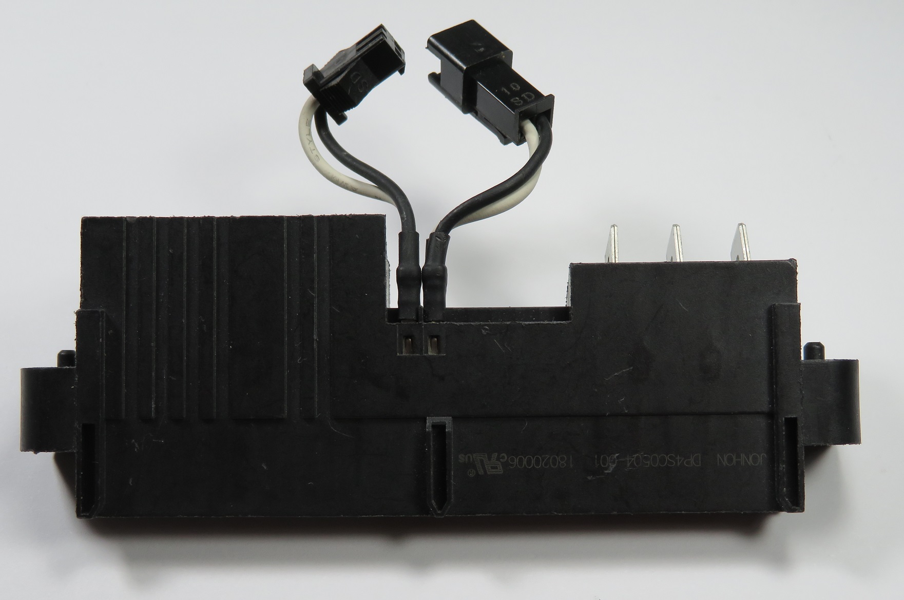
On the bottom of the connector is the part number. It appears to be a connector from Chinese manufacturer Jonhon. The part number is DP4SC0504-001.
The drawing doesn’t include the flying lead connectors for the CAN or Slot Detection, only making mention that there are five signal contacts with wires and termination when customised.
The connectors appear to be JST SM connectors. The female is the Slot Detection (‘on/off’) connection, while the male is the CAN Bus. You can choose to purchase some, or cut them off and add your own. For the time being, I have shoved a 0.1″ header into the Slot Detection.
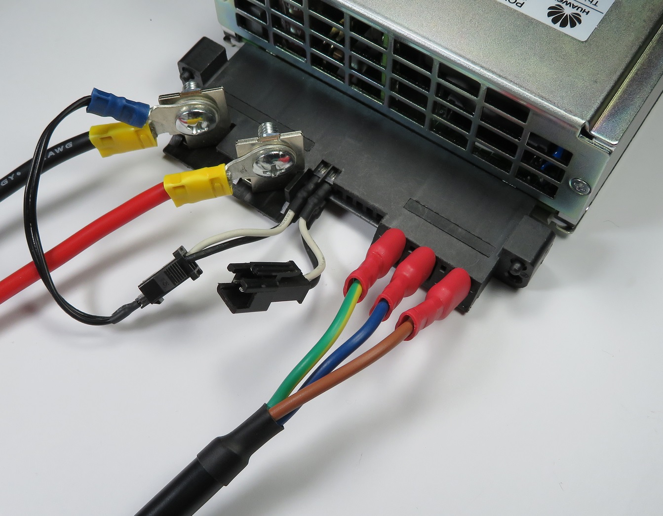
To enable the power supply, connect both the slot detect 1 and slot detect 2 pins to OUTPUT- (negative).
While not mandatory to enable the output, you should also connect Pre-Charge to OUTPUT-. For those using the DP4SC0504-001, the Pre-Charge is wired internally to the OUTPUT-.
At this stage, you should have a dumb 53.5V, 56.1A power supply unit.
CAN Interface & Protocol
The CAN interface operates at 125kbps with extended 29 bit identifiers.
On power up, the unit will send out unsolicited packets and this can be useful in ensuring your hardware is working correctly.
Statistics
To request statistics such as the Input Voltage/Frequency/Current, Output Voltage/Current, Efficiency etc. one can send a single eight byte zero padded frame to the CAN address/ID 0x108040FE. The device should respond with a series of frames with ID 0x1081407F conforming the following format:
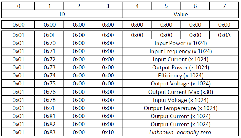
The 2nd byte in the frame appears to indicate what parameter is being sent. The parameter’s value is contained in the last four bytes with byte 7 being the least significant byte.
For example, this is a output from candump:
  can0  1081407F   [8]  01 0E 00 00 00 00 00 0A
  can0  1081407F   [8]  01 70 00 00 00 01 A6 84   (Input Power)
  can0  1081407F   [8]  01 71 00 00 00 00 C8 0A   (Input Freq)
  can0  1081407F   [8]  01 72 00 00 00 00 01 C2   (Input Current)
  can0  1081407F   [8]  01 73 00 00 00 01 80 8E   (Output Power)
  can0  1081407F   [8]  01 74 00 00 00 00 03 A4   (Efficiency)
  can0  1081407F   [8]  01 75 00 00 00 00 D5 C8   (Output Voltage)
  can0  1081407F   [8]  01 76 00 00 00 00 04 6A   (Maximum Output Current)
  can0  1081407F   [8]  01 78 00 00 00 03 C0 80   (Input Voltage)
  can0  1081407F   [8]  01 7F 00 00 00 00 64 00   (Output Stage Temperature)
  can0  1081407F   [8]  01 80 00 00 00 00 70 00   (Input Stage Temperature)
  can0  1081407F   [8]  01 81 00 00 00 00 07 B2
  can0  1081407F   [8]  01 82 00 00 00 00 07 32   (Output Current)
  can0  1081407E   [8]  01 83 00 10 00 00 00 00
Note: It’s currently not known what the two different (0x81 & 0x82) current parameters are. I personally find 0x81 is more accurate compared to a bench meter in series with the output. If you know more, please leave a comment below.
Setting Values
To set either the output voltage or current limit, send a frame to 0x108180FE with the following format:
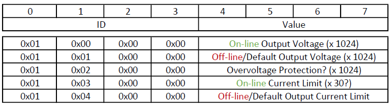
Again, the 2nd byte in the frame indicates what parameter is being set.
The power supply should acknowledge the command with a packet of ID 0x1081807E. The ack frame should have identical contents, except if an error has occurred, in which case the first byte contains 0x21.
If the set value is out of range, an error will be flagged. This is a useful way of determining the range of acceptable values.
Modes of Operation
The power supply can operate in two different modes – we call this on-line and off-line.
Off-line is when there is no CAN communications – i.e. the power supply is operating in standalone mode. Off-line values are non-volatile and also used as the default value when the power supply first powers up.
On-line is when there is valid CAN communications addressed to the power supply. This mode will time-out approximately 60 seconds after the last CAN message and will be indicated on the front panel via a flashing yellow alarm indicator.
On-line values are volatile and set to the default values upon entry into this mode.
Therefore, if you send a command to set the on-line output voltage (0x00), the output voltage should be reflected immediately. If no further messages are sent (to any valid CAN ID), the output voltage will return to the default off-line voltage after approximately 60 seconds. Provided a valid CAN message is sent within the timeout period, the output should remain equivalent to the on-line output voltage parameter.
To date, I’m unaware how to read the above parameters back. If you know more, please leave us a comment below.
Specifications
While the data sheet indicates the output voltage is adjustable from 42~58VDC, different ranges exist between on-line and off-line:
- Output Voltage – Online – 41.5 to 58.5 volts, 0.1A steps
- Output Voltage – Offline – 48 to 58.5 volts, 0.1A steps
- Current Limiting – 0 to 60A, 0.1A steps
Reference Software
To test the protocol, I have developed some reference software at https://github.com/craigpeacock/Huawei_R4850G2_CAN
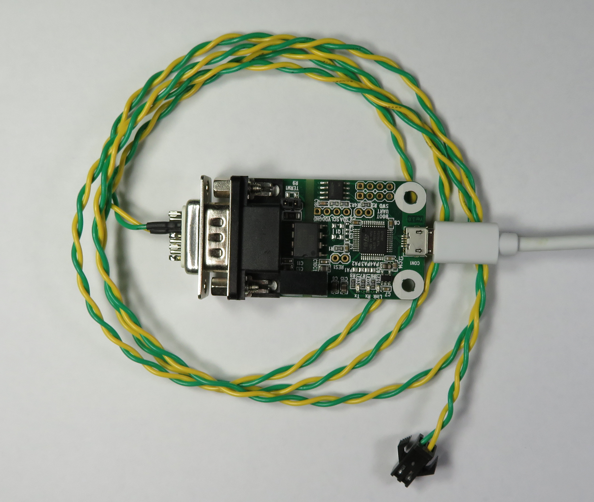
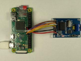
It takes advantage of the Linux SocketCAN interface meaning you can use it on a Linux Desktop with an appropriate SocketCAN CAN Interface Adapter, or on embedded platforms such as the Raspberry PI / Beaglebone with suitable controllers/transceivers.
The software can be used to set the output voltage and maximum current:
Huawei R4850G2 53.5VDC 3000W Rectifier Configuration Utility V1.1
http://www.beyondlogic.org
Usage: r4850 [options] <CAN interface>
Options:
	-v <voltage>	(Set Power Supply Voltage)
	-c <current>	(Set Maximum Current)
	-s              (Save settings to non-volatile memory/off-line)
And report statistics:
Input Voltage 237.88V @ 50.03Hz
Input Current 0.41A
Input Power 98.18W

Output Voltage 47.98V
Output Current 1.97A of 37.70A Max, 0.002Ah
Output Power 89.36W

Input Temperature 27.0 DegC
Output Temperature 27.0 DegC
Efficiency 91.0%
Battery Charging
The current limiting on the R4850 makes it perfect for charging 48V battery packs.
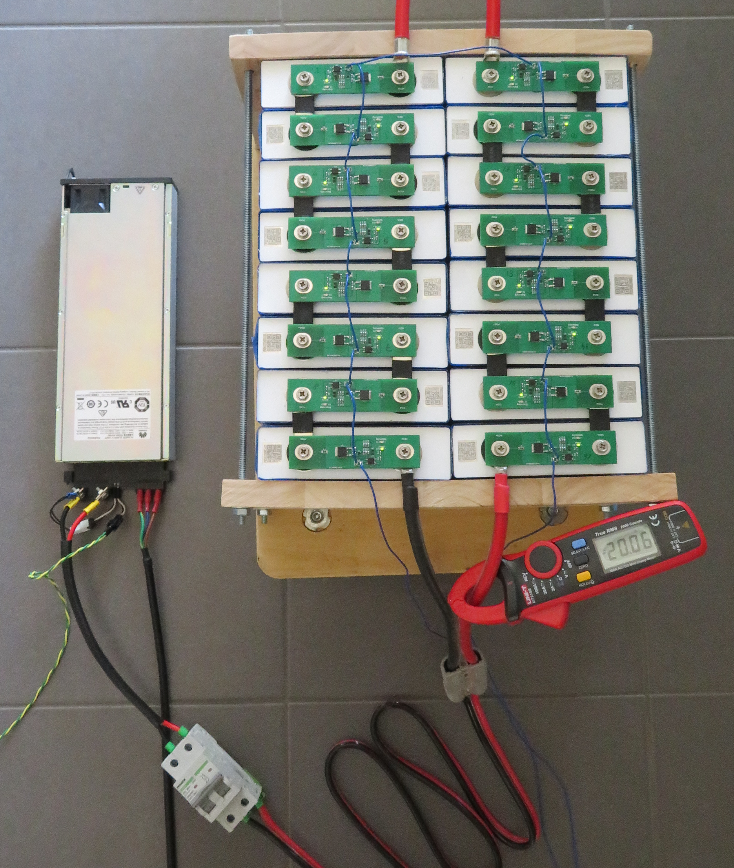
Huawei R4850G2 53.5VDC 3000W Rectifier Configuration Utility V1.1
http://www.beyondlogic.org

Input Voltage 237.34V @ 49.98Hz
Input Current 4.86A
Input Power 1154.06W

Output Voltage 55.01V
Output Current 20.32A of 20.00A Max
Output Power 1110.10W, 5.230Ah

Input Temperature 22.0 DegC
Output Temperature 38.0 DegC
Efficiency 96%
Thanks for posting this information. I’m considering buying several of these to use in series and parallel as a general purpose high-power system power supply. Did you have any luck figuring out how to parallel them and enable the “current sharing” feature? Do you know if there’s anything special that needs to be done to connect them in parallel?
Thank you for your sharing. I have a huawei monitor module. I will do some test to capture the communication between the power supply module and monitor module. Do you have any comments?
Hi, I’m trying to do exactly the same thing with a PMU 11A and OLT SmartAX MA5800X7 through ESC port. I’m using two RS485-to-USB adapters and a software serial analyzer. Have you made any progress?
I know that this power supply has a control system based on Bluetooth app in China. I am trying to crack this system. If anyone is interested, please contact me and I also need some help
i receive a new r4850g2 and i connect to 240 v no load connected the fan running very fast speed no hot temperature the power supply is cold and the first yellow led blinking is it ok normal?? i not have a canbus connected i use for my ldmos amplifier
Be aware that default output is 53.5V and MRF300 can have maximum 54V. To run it standalone without power adjust please see my YouTube at Pa3fxo and Huawei R4875 to see pins connected to earth to get it running.
How can we connect 2 of these power supplies in parallel?
Same question here too. Got some on order, once they arrive I will do some testing. Anyone had success connecting multiples in parallel?
I would appreciate if you could keep us updated on your results connecting these power supplies in parallel
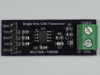
I get confused with the can connection. Pictuers show CAN-L at the bootim of the finger PXB but table says top.
Erik, good pick-up. The CAN-L is on the top side, hence the table is correct. I’ll get the pictures fixed shortly.
Ran into the same problem. Had me worried for a minute.
Perhaps just remove the wrong pics?
Thanks for the article.
Is it possible to change the voltage from 53.5 to 57v?
yes. up to 58.5V with the script and with a CAN interface
Hello,
can anyone confirm whether it’s possible to run a CC slope (eg. 1A~60A) when CV operation (3.6V per cell -> 57.6V for 48V setup) for soft ramp battery loading?
Or will the PS just operate at full output current (60A) when battery is nearly empty and CV operation at 57.6V is set?
As you wrote. This power supply have CC limit, it can go from 0V to 58.5V with eg 1A current limit. (But fan below some ~40V goes full speed crazy turbo jet :))
HI – great documentation !
The “can0 1081407E [8] 01 83 00 10 00 00 00 00” looks like a flag or status register. Examp: 0x00000200 -> Standby (via Pin, open/3.3V)
And I also use x20 for output_current_max.
Peter
Hi, does anyone know if the other models of Huawei R48xx or the Emerson or Eltek 48V telecom units use the same CANbus communications registers as the R4850G2? Thank you. –Jim N8ECI
Hi Jim, Im trying to figure out the same I have an off brand and I found that mine runs at 250kbps, but cant seem to get anywhere else. I have data that looks like this…
msgid: 8bc0048 data: protoId: 11 addr: 3c cmdId: 00 fromSrc: 00 rev: 24 count: 00 | DATA: 03 00 00 0e 00 3b 03 ea
What would be the cause of the 0x21 error when I try to set the offline voltage? I can set the online voltage just fine. Thanks, JB
I use an Arduino Nano and an CANBus WB-184 (MCP2515) module to communicate with the Huawei R4850G2.
Setting output voltage works but
i try to get actual status by request data frame via can.SendMsgBuf to 0x108040F. My problem right now is that i get some response but not all data from 0x0E,0x70 ~ 0x83. Instead it looks like i only get every x-th frame, ie. 0x70, 0x73, 0x78, 0x82).
The communication speed is as mentioned 125kb/s; higher speeds result in no communication.
Could it be that the 8MHz of the CanBus oscillator is a problem here?
Hey Markus, I am just looking into this myself. Would you care to share your code?
I have a CANBed FD (Atmega32U4 with CanFD/ Can 2.0) at hand
Hello! I have arduino nano + mcp2515 CAN 8MHz from aliexpress. The output voltage setting commands work fine, the response with the rectifier status is also with dropped frames like yours. Did you solve the frame drop issue?
Send me video Arduino
Markus, it is possible have the arduino code to set the output voltage?
I have MCP2515.
Thank you. Alessandro
I’ve put my arduino port here for your convenience: https://github.com/haklein/r4850g2_arduino/blob/main/r4850g2_V2.ino
The likely reason is that you do miss CAN frames, same happened to me by use of Serial.print() statements in the on Receive handler (aruduino-CAN fork from adafruit on a Mega2560)
Hi Markus! I have an ESP8266 + compatible Shield for Wemos D1 mini with mcp2515 CAN 16MHz from kleinanzeigen.de
Works like a charm. 🙂
Robert
Thanks, Craig for the detailed information on this specific PSU.. I am using this PSU for a 48volt LDMOS RF Amplifier kit that I am currently building and this information is most helpful. Thank you once again. Will
Is there a way get the power supply out of hibernation as I recently bought one but the indicator lights show its in hibernation
Any help would be appreciated thanks.
Is it possible to charge a 24V Battery Lifepo4 with this power supply? Does it take damage of this mode? I tested for a short time, and the Data Sheet also says 35Amps possible with 24V. The fan went up to maximum and it worked, but I dont know if this is good for the electronic.
Any experience?
huh? voltage never goes below 41V
Just a note on the current set command: amperage is NOT multiplied by x30 but x20 instead.
Thanks David. That was my observation as well.
https://github.com/craigpeacock/Huawei_R4850G2_CAN#user-feedback-on-maximum-current
Hi, Craig can you share what boards are you using for each battery cell (seen on the last photo)? Thanks, Tish
Tish, The single cell BMS attached is an in house design created during the chip shortage. I was intending on publishing it, but it has one deficiency with current capacity of the balancing circuit.
Hi
Its possible to change the CAN-address of the device? Or need I do so? I connect three power parallel and connecting input power to three phase net at star… May be need own CAN- line to each power?
Hello,
I would like to use the power pack as an additional charger for a Voltsmile LiPo battery 51.2 V 100Ah battery when the solar power is not enough and there is a power failure. Can the power pack communicate/control via the CanBus with a VictronMulti II 48/5000/70-50 (e.g. charging current control when the battery is full?). A digital inverter generator with a rated output of 3.2 KW (max. 3.5 KW) supplies the electricity in an emergency.
Or can the charging current only be preset?
Thanks for your insights!
Hallo,
ich möchte das Netzteil als zusätzliches Ladegerät für einen Voltsmile LiPoAkku 51,2 V 100Ah Akku verwenden wenn der Solarstrom nicht langt und Netzausfall ist. Kann das Netzteil über den CanBus mit einem VictronMulti II 48/5000/70-50 kommunizieren/gesteuert werden (z.B. Ladestromregeln, wenn Akku voll?). Den Strom im Notfall liefert ein digitaler Invertergenerator mit 3,2 KW Nennleistung (max. 3,5KW,)
Oder kann der Ladestrom nur fix voreingestellt werden?
Danke für Eure Erkenntnisse!
Nein, aber nimm ein Arduino+CAN-Bus modul
Can I only charge a battery with this or can I use the Huawei_R4850G2 also to discharge the battery?
I’m not aware of anyway to discharge the battery with the R4850G2. It doesn’t act as a load or bi-directional charger (discharging into the grid).
Is there a way to control the fan speed? i.e. adjust when load or temperature increases?
I’m using it on a LDMOS RF power amp.
Is it possible to change the voltage to 87.6v?
Can anyone confirm these could also work in series for 200-600+V application for instance with 4-12 units in series?
Is there a case for the R4850G2 with a good cooling for using the full power continuous ?
I have build my own case from HDF with 2 Fans, and many holes on all Walls, but it get to hot >71C when i use more then 2000w.
Yes, here is: AC-DC Power Towaaa (*Star Wars Music Intensifies*)
https://ibb.co/gSs4t0S
https://ibb.co/bQ2ncMy
https://ibb.co/R3PBJhK
https://ibb.co/Xt6CrGQ
Get yourself these self adhesive cooling plates here: https://amzn.to/4aeaF26
(you need 12 pieces)
and add three Arctic P8 Max: https://amzn.to/4afYm5c
You’ll get around 70°C with 3000W, at 2000W probably 45-50°
I’m looking for information on the RS485 version, sometimes referred to as R4850A or PSU4850. I have a couple and was very disappointed when I realised they don’t have as much in common with the R4850G2 as I expected…
Anyone have pointers for me?
I managed to get it running parallel to a victron MultiPlus-II 5000.
Now I’m able to push over 100A instead of 70A into my pylontec 19kwh.
I’ve used esp and can interface together with Herzschlag firmware from bavarian powerguy.
Now it’s also connected to my homeassistant and I send ip commands to set the voltage to 52V and current from 0A to 35A in steps of 5A.
I just start with 5A when the mp2 charges over 2500W.
For cooling I use 3 Fans with temperature sensors from Arctic.
I’m very happy with it.
I have connected 3 in parallel, how ever when current is drawn when load is connected, it is not uniform. I am trying to pull 55v and 150 amps. Dose anyone have an idea how can we can balance the output current in a way where the output current from each rectifier is uniform or the same ?
Did anyone tried the R48100G1? Does it use the same CAN protocol as the R4850G2?
Um, that beast only accepts 3-phase 400Vac as input power. Do you have that around your house?? I sure dont.
Great info. I found one on Ebay for $156 USD with free shipping. I also found the Jonson connector for $12.
I found another basic CAN utility and programmed it for 57.0 VDC
Its powering an LDMOS HF amplifier in which the FETs prefer 55 to 60vdc for the Vds.