

Motivation
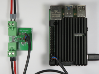
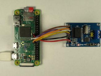
I have had the requirement to back-up small 5V low-powered devices such as a Foscam C1 security camera and a Raspberry PI based LoRaWAN concentrator.
Many commonly available 5V Uninterruptible Power Supplies feature a two chip design with a Li-Ion battery charger to charge the back-up battery, and boost converter to step up the battery voltage back up to 5V.
Like most of my personal designs, cost was not a primary driver. I was on the search for a elegant, preferably single chip device that was fit for purpose.
Lithium Ion batteries can be stressed when left at full charge for long periods of time. As the UPS would remain on standby with fully charged batteries most of the time, a device that took this into consideration would be just the fit.
I would eventually settle on the LTC4040, a 2.5A Battery Backup Power Manager from Analog Devices.
The LTC4040 has an external power path that powers the output directly from the input when power is available. In the event of loss of external power, a step-up DC-DC converter generates 5V from the single cell Li-Ion or LiFePO4 Battery. When external power is available, the step-up regulator operates in reverse as a step-down battery charger.
With the easy part of the design down, it was time to concentrate on the hard part – the connectors.
Connectors
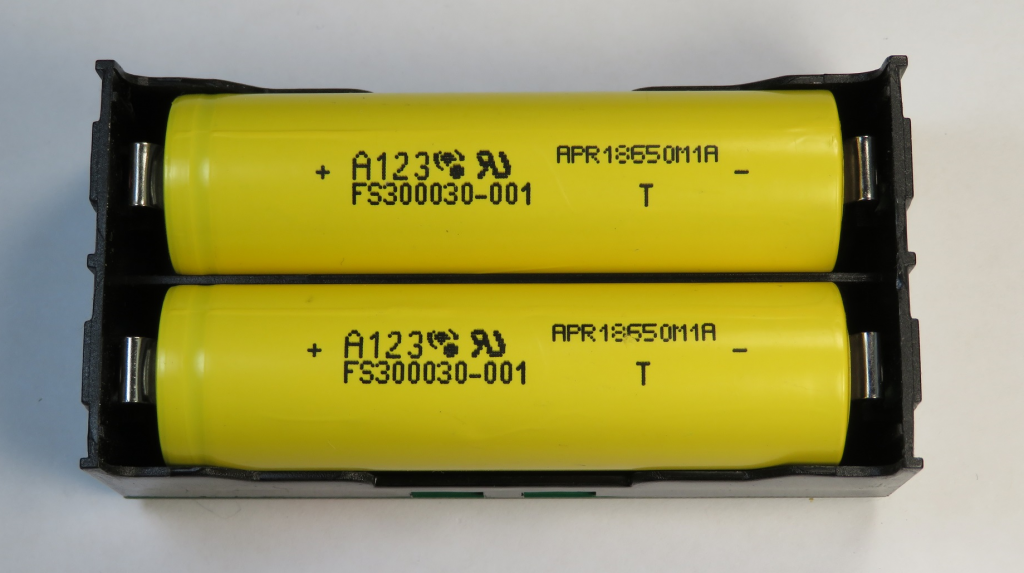
The PCB for this project will mount directly to a dual 18650 battery holder, hence it is not ideal to have through-hole leads protruding from the bottom of the PCB. But, it is still acceptable to have TH (through-hole) registration pins commonly found on SMD (surface mount device) connectors, provided they don’t protrude further than the bottom face of the PCB.
The connectors also need to fit in between the fixed battery terminals found on the edge of the board. The inner four mounting holes of the battery holder are superfluous and can be removed.
I had a handful of 5V plug-packs kicking around with 1.3mm DC sockets. So it seemed the obvious choice, I thought, to use a SMD 1.3mm DC socket. I had even ordered the Wurth 694103107102 DC Power Connector with a 5A current rating.
Both the Raspberry PI and security camera use USB Micro-B connectors for their input power.
At first, a USB Type A connector appeared the most logical connector for the output. But, Type A connectors have a reputation for being unreliable at moderate currents. Datasheets for Type A connectors commonly specified a maximum current between 1 and 1.8A, although I did find the odd one rated to 3A. Many cables also have poor current carrying capability resulting in unacceptable voltage drops. It would also be a squeeze to get a SMD Type A connector in between the battery terminals.
At this stage, I had temporarily parked the design with a plea for help choosing a connector, while working on the next project to half complete.
“USB C is the perfect connector”
My plea would soon be answered by the Circuit Maker community. Jason commented on the 11th January, ” USB C is the perfect connector.”
At first I was sceptical. I was worried about finding suitable and non-expensive cables – by this I mean USB-C to USB Micro-B with a length around 30 to 50cm that didn’t cost an arm and a leg.
But, Amazon would allay my doubts with a 30cm Fasgear USB-C to USB Micro-B cable for around $6 USD. They even had a 50cm Fasgear USB-C to USB-C cable for the new Raspberry Pi 4 for around the same outlay.
Schematics
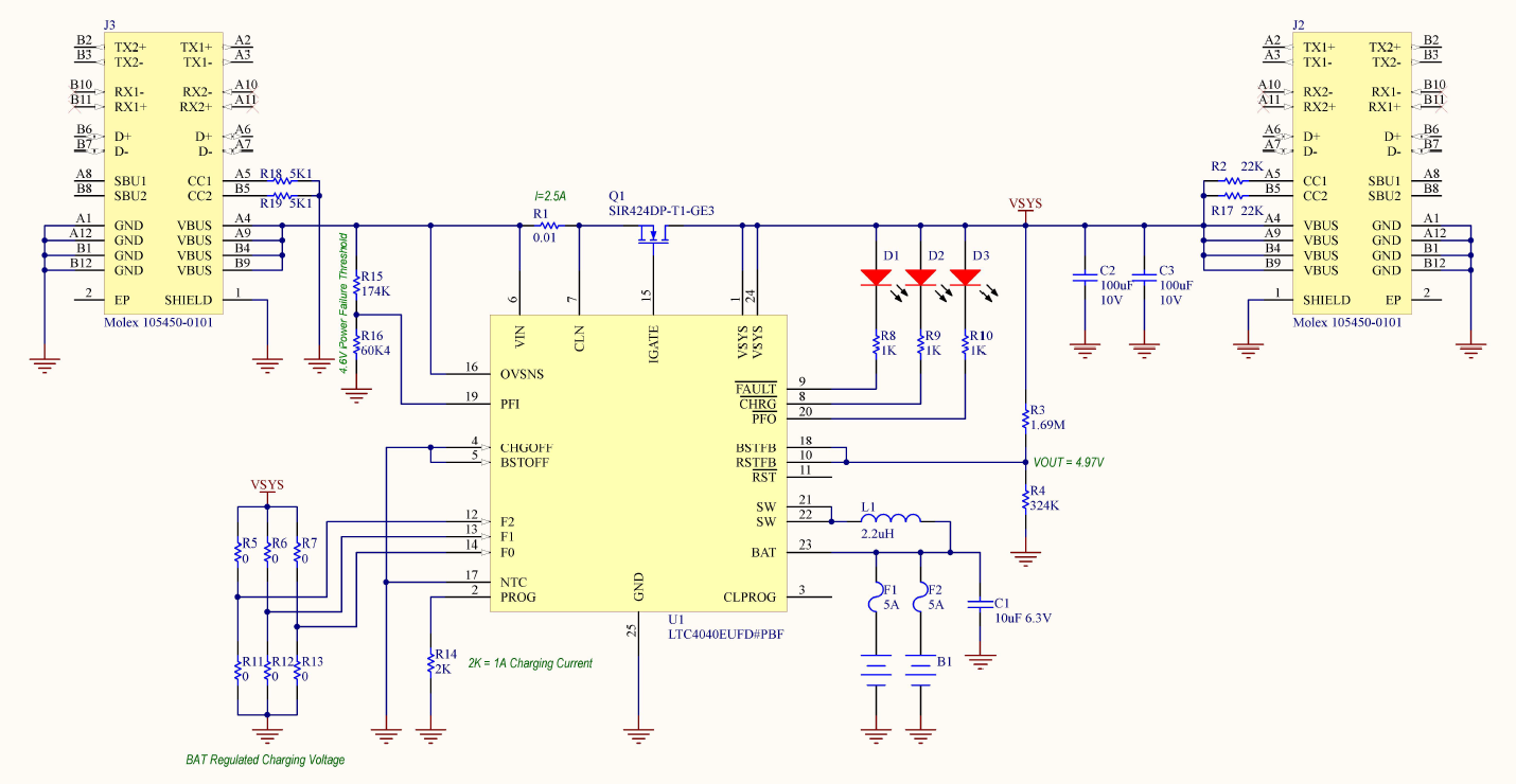
Battery Chemistry and Charge Voltage
The battery chemistry and charge voltages can be set up via inputs F0, F1 & F2. For Li-Ion cells, regulated charge voltages of 3.95V/4.0V/4.05V/4.1V can be selected. For LiFePO4 cells, these thresholds change to 3.45V/3.5V/3.55V/3.6V.
As the batteries are used for back-up purposes and as capacity is degraded when cells remain fully charged, it is recommended to trade off capacity (up-time) for battery lifetime.
Charge Current
A fixed resistor on the PROG pin, sets the maximum charge current. The current design uses a 2K resistor to set the charge current to 1A. The LTC4040 includes a safety timeout or approximately 4.25h for Li-Ion batteries and 2.13h for LiFePO4.
The current shunt (R1) can be used to prioritise system load over the charge current, ensuring the input power supply is not overloaded. At present the 0.01 ohm shunt sets the maximum input load to 2.5A (0.025V/0.01). This means, if the load is drawing a full 2.5A, the charger will be throttled back to almost nothing. You can change R1 to 0.007 ohms to set the current at 3.5A. This allows the battery to charge at 1A, while the load can consume 2.5A.
Backup / Power Failure Threshold
R16/R15 sets the power failure threshold at 4.6V. When the input exceeds 4.6V, the device will operate in pass-through mode (via external Q1 MOSFET) and the output voltage will track that of the input. When the input voltage drops below this threshold, the DC-DC converter will switch on and power the load from battery. In this mode, the output voltage is set via R3/R4 to 5.0V.
Design Files
Design files can be downloaded from the Circuit Maker website. Circuit Maker is a free EDA tool from Altium.
The PCB for this design was fabricated by jlcpcb.com.
Great device! Thanks for the idea, I will do myself the same.
Hi Patrik, I am looking to replicate this elegant design of yours and then expand on it to manage more cells in parallel to extend battery life. The only unknown in my way is how the PCB interfaces with the cell holder? I would like to integrate this UPS into my EE capstone project so I would appreciate if we can discuss further.
Raad,
The battery holder is the BK-18650-PC4. It has a few pins that solder directly into the PCB.
Regards,
Craig
Thanks, just what I was looking for. Can you also share how much testing you’ve done?
Hi. Do you by any chance have one spare board to sell?