

Single Wire CAN (SAE J2411) is commonly used in cost-sensitive Automotive applications where speed and cable length is not as onerous.
It is also useful in applications were a traditional CAN differential pair is physically not possible.
For example, on Type 2 Mennekes connectors used for Electric Vehicle (EV) charging, the communication between the supply equipment and the vehicle is performed via a PWM signal on a single Control Pilot (CP) pin in respect to earth. Tesla has used SWCAN to digitally communicate over this single pin.
Various SWCAN drivers are available and generally share the same compatible pinout (SO8 and SO14):
- OnSemi NCV7356
- Melexis TH8056
- Philips AU5790 – Obsolete.
- NXP (Freescale) MC33897 – Only available in 14SOIC.
- Infineon (Siemens) TLE6255 – Obsolete – Only available in 14SOIC.
The typical data rate for normal communication is 33.3 kbits/s and for high-speed communication, 83.3 kbits/s.
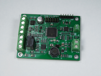
This breakout board is for the SO8 variant.
Design Files
Design files can be downloaded from the Circuit Maker website. Circuit Maker is a free EDA tool from Altium.
- Open in Altium 365
- SWCAN Breakout version 1.A.1 Gerbers – PCB (Zip)
- SWCAN Breakout version 1.A.1 Schematics (PDF)
- SWCAN Breakout version 1.A.1 Bill of Materials (XLSX)
The PCB for this design was fabricated by oshpark.com.
Great project! I am looking to decode as well as emulate a Tesla EVSE side interface for DC charging (only control messages for the time being and see if I can get some good info from my Telsa EV that is still using non-NACS SW CAN. I came across your github repo and wanted to see if you have been able to successfully connect/decode messages. Also do you sell the above SW CAN breakout board (and if so where can I get it from) – also does it work with Linux based platforms like RPi? I see you have it working with Beaglebone so hopeful. any details and info appreciated… Can’t seem to find much info on Tesla SW CAN more on NACS as it’s being standardized and comply to ISO15118 but legacy cars will still be on the older ECU and protocols…
I suspect you have been looking at the https://github.com/craigpeacock/Tesla-ChargePort-Decoder repo. As for successful communications, maybe have a look at https://github.com/craigpeacock/dsPIC33EP_IEC61851_J1772_ChargePort_EVSE. There should be an output using SWCAN Mode. It’s by no means complete, but it is successfully establishing digital communications and talking.
dsPIC33EP128GS804 IEC61851/SAE J1772 Demo Code
00000.14 PP: 3.30V (ADC_4095) Port unplugged
00005.11 PP: 1.90V (ADC_2361) 32A detachable cable detected
00005.30 CP: No signal present
00005.43 CP: Duty cycle = 4.8% @ 1000.1Hz
00005.46 Requesting digital communication
00005.58 Enabling SWCAN Interface
00005.60 0x505 [8] 0B 86 00 00 00 00 7D 08
00005.62 0x32C [8] 00 01 BF DC C0 C0 1C 05
00005.62 0x47C [8] 00 00 00 00 00 00 00 00
00005.62 0x505 [8] 1F EC 7F B8 08 42 08 00
00005.65 0x31C [8] 10 05 F6 78 FE FF 07 00
00005.65 0x505 [8] 00 03 CB 2D 2D 09 04 00
00005.72 0x31C [8] 10 05 F7 78 FE FF 07 00
00005.72 0x505 [8] 0B 86 00 00 00 00 7D 08
00005.79 0x31C [8] 10 05 F6 78 FE FF 07 00
00005.79 0x505 [8] 1F EC 7F B8 08 42 08 00
00005.86 0x31C [8] 10 05 F7 78 FE FF 07 00
00005.86 0x505 [8] 20 A4 11 F7 6C 04 00 00
00005.93 0x31C [8] 10 05 F7 78 FE FF 07 00
00005.93 0x505 [8] 00 03 CB 2D 2D 09 04 00
00006.00 0x31C [8] 10 05 F7 78 FE FF 07 00
00006.00 0x47C [8] 00 00 00 00 00 00 00 00
00006.00 0x505 [8] 0B 86 00 00 00 00 7D 08
00006.05 0x32C [8] 00 01 BF DC C0 C0 1C 05
00006.05 0x505 [8] 1F EC 7F B8 08 42 08 00
00006.10 0x31C [8] 10 05 F7 78 FE FF 07 00
00006.10 0x505 [8] 20 A4 11 F7 6C 04 00 00
00006.17 0x31C [8] 10 05 F6 78 FE FF 07 00
00006.17 0x505 [8] 00 03 CB 2D 2D 09 04 00
00008.13 PP: 3.30V (ADC_4095) Port unplugged
I have only attempted AC charging as I can eave drop on a UMC and TMC. I can’t say I know anything about DC charging and if the SWCAN protocol is actually used for this.
Thank you very much for providing the relevant details. I have been tinkering and am able to talk to a Chevy Bolt via CCS1 over v2g/ipv6/greenphy once the PWM is set to approx 5% (signaling DC mode to the PEV). But the legacy Teslas that haven’t moved or paid to move to the new NACS are still on the older SWCAN based signaling (is what I’ve read – to be tested). I was searching up on the SWCAN (I’ve no experience with SWCAN but have used normal CAN and with Linux/RPi using socketcan interface – hence trying to understand how to get the pins on your board (is it UART?) working with something like RPi with a socketcan type interface… as it gives lot of flexibility to use python and cantools, etc.
Thx again
Hi Craig – How do you connect your decoder to the PEV/EVSE side to take the trace? Do you tap into the CP line of the interface or use an inductive coupler that can listen in on all the electrical signals and convert them to SWCAN?
I saw a potential solution and folks sharing images of the tool that can listen in on the messages on the wire and decode if the freq is kept at the same one as what SWCAN uses… https://www.picoauto.com/support/viewtopic.php?t=22544
Appreciate your insight.
If you want to eaves drop on the SWCAN communication, I found connecting it to the CP line via a resistor did the trick. (And GND to PE)
i.e. Connecting via a resistor didn’t load the bus so much that communication stopped. I can’t remember what the resistor value was – try maybe 100k.
Thank you – I’ve ordered the components and board for your SWCAN Transceiver Breakout Board. Hope to get it up and running by end of next week (once the parts make it).
Will try to sniff the CAN messages from the Tesla CP/PE side as you mentioned above. Can this board also be used with a Raspberry Pi – I see you have an example with Beaglebone Black, but I’m trying to see if I could get it working with a Pi.
Also, my next goal is to try and inject CAN messages to the EV using the module using the Linux SocketCAN lib. I couldn’t find a DBC for Tesla charging but will try to replay some of the messages you mentioned above. Will this module work for that use or for that I have to use https://github.com/craigpeacock/dsPIC33EP_IEC61851_J1772_ChargePort_EVSE ?? I have the other components working to get the 5% duty cycle as well as the PP etc connected. My main goal is to get the DC commm going over SWCAN.
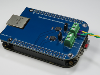
It can be used with the Raspberry PI, but you will need an external CAN controller. What you have above is a CAN Transceiver only, not a controller. The Beaglebone Black has an inbuilt CAN Controller, hence why I default to it. On the Raspberry Pi you need to add an external controller, something like the MCP2515:
https://www.beyondlogic.org/adding-can-controller-area-network-to-the-raspberry-pi/
Thank you again. This helps explain and clears my confusion. For now I have ordered a Beablebone Black and will replicate your env to get started (eventually want to move to RPi but will wait to get going).
My other question is can I use this breakout transceiver and Beablebone MCU/CAN controller to also send messages to Tesla EV (emulating charger using the same set of messages you have in https://github.com/craigpeacock/dsPIC33EP_IEC61851_J1772_ChargePort_EVSE
I looked at that project my goal is to emulate the EVSE/charger side SWCAN communication for DC (have the other connector parts and voltage/duty cycle taken care of on an Arduino. If that’s possible it would give me a head start on SWCAN side . /if possible, start with copy your CAN Tx/Rx messages as shown in that code and send them over this CAM Transceiver
I suspect you would be missing the initial IEC61851 Digital Negotiation. I’m not aware of a way to immediately talk to the Car without first generating the 1kHz signal on the control pilot to request digital communications. That’s not to say it doesn’t exist, but I have monitored both a UMC and TWC talking SWCAN, and both start with the IEC61851 1kHz signalling.
What you are probably wanting to strive towards is something like
https://www.beyondlogic.org/prototype-iec61851-j1772-evse-interface/
in a BeagleBone Cape. I think you can get the BBB to generate a 1kHz control pilot signal.
Yep that’s the intent. I’ve been able to get the 1khz and 5% duty cycle etc (to have the EV start DC mode) done outside via an esp32. But after that point I can’t get anything hence want to get this swcan interface so I can sniff and later send the correct messaging via BBB. Also where did you find the message translation for the can messages for Tesla charging. Did you reverse engg them or are they available somewhere. Thx again.
Hi Craig – with your insights and doc on bringing up CAN interfaces on BBB – I was able to get things moving. I have ordered the parts for this SWCAN module as well as boards (just came in). Can I take 2 boards and connect them b2b similar to what I have today for CAN loopback testing – and should be able to see CAN messages from one to the other if even when using 2 interfaces. Want to make sure they’re up and running before connecting it to the charge port of my Tesla model 3 – that has not been upgraded to CCS yet.
Sorry one last question, what do we need to connect to the. VIO pin? 5v or can we leave it disconnected? I see they’re somehow tied to mode 0 and 1 pics of the chip but not sure if they can be left as is out need to be connected? There was no such pin on the standard can bus transceiver. Hence a bit confused. Thanks again.
The VIO pin sets the logic level and should be tied in your case to 3.3V (Beagle has 3.3V logic). The RXD pin on the NCV7356 is open drain, so VIO drives the pull up resistor.
Hi Craig – I finally got all the components and built 3 setups using the links you have provided above. I am connecting them in b2b mode – sending random CAN pkts using cangen on can1 interface and trying to get them on can0 – but I don’t see any pkts recv. My understanding is that this should work similar to normal CAN transceivers – correct? I had them running b2b on the same setup so just replaced them with the SWCAN boards on the beaglebone black. I am not sure why I don’t see any pkts recv (unless I’ve messed up the connections on the leads).
2 Questions for you:
1. VCC – 3.3V correct?
2. VIO pin – where does this go on the Beaglebone Black? For now, I’ve left it disconnected.
Appreciate your help in advance. Please let me know if back2back can work for SWCAN or not – it does for std CAN and I’ve kept the pins for Tx/Rx in the same place so that there’s no confusion.
Only other diff is I’m setting the speed in the CAN init as 33300 kbps v/s 500000 kbps for std CAN.
Thx.
Yes, I would expect them to work ‘b2b’ – essentially they are just three different nodes on your CAN bus.
Given VIO is currently disconnected, I suspect the open drain RXD pin never goes high. Probably once you connect VIO to 3.3V, things should start to work.
Thank you very much I tried it and works great. Thank you again. I’m now looking at your other evse charger side project and trying to understand the messages and values the charger needs to send and message transaction. For now I’ll try to sniff the messages from the real charger and EV. Hopefully it’ll let me get further. Thank you again for the awesome projects and details you’ve covered.
Hi Craig – got some good progress using your transceiver board. Was able to connect it to the Tesla chargeport connector and wall charger and sniff out SWCAN messages. Was also able to use your decoder with some more mods and decode some values.
Problem was some of the messages weren’t decoded although they are same IDs as the one in the excel spreadsheet on your Github. What is the reference for these messages – is someone actively decoding these, I don’t think Tesla has opened up this spec correct?
Here are some messages and their decodes as part of the trace collection.
ChargePort Packet Decoder
Unexpected data in can_id 0x102:00 00 00 00 02 2B 00
0x30C: EVSE power disabled
0x302: SoC = 89.8% Unknown flags 42
0x235: [Byte 5 = 02102] [Byte 6 = 01F02] HV Battery 394.6V Current -0.4A
0x202: Byte 2 = 0x15 Byte 5 = 0x02, AA = 12 DD = -20
0x213: CC = 0 AA = 0 [Not Charging]
0x112: CC = 0
0x123: [Byte 4 = 03F02] CC = 0
0x31C: TWC Advertising 48.0A @ 2V
Unexpected data in can_id 0x31C:60 04 02 60 04 08 00 00
Unexpected data in can_id 0x214:00 00 00 60 00 C0 00 00
Unknown frame can_id 0x31D:00 00 00 00 00 00 00 00
Unknown frame can_id 0x31D:00 00 00 00 00 00 00 00
Unexpected data in can_id 0x102:00 00 00 00 02 2B 00
0x30C: EVSE power disabled
0x302: SoC = 89.8% Unknown flags 42
0x235: [Byte 5 = 02102] [Byte 6 = 01F02] HV Battery 394.6V Current -0.4A
0x202: Byte 2 = 0x15 Byte 5 = 0x02, AA = 12 DD = -22
0x213: CC = 0 AA = 0 [Not Charging]
0x112: CC = 0
0x123: [Byte 4 = 03F02] CC = 0
0x31C: TWC Advertising 48.0A @ 2V
Unexpected data in can_id 0x31C:60 04 02 60 04 08 00 00
Unexpected data in can_id 0x214:00 00 00 60 00 C0 00 00
Unknown frame can_id 0x31D:00 00 00 00 00 00 00 00
Unexpected data in can_id 0x102:00 00 00 00 02 2B 00
0x30C: EVSE power disabled
0x302: SoC = 89.8% Unknown flags 42
0x235: [Byte 5 = 02102] [Byte 6 = 01F02] HV Battery 394.6V Current -0.5A
0x202: Byte 2 = 0x15 Byte 5 = 0x02, AA = 12 DD = -26
0x213: CC = 0 AA = 0 [Not Charging]
0x112: CC = 0
0x123: [Byte 4 = 03F02] CC = 0
0x31C: TWC Advertising 48.0A @ 2V
Unexpected data in can_id 0x31C:60 04 02 60 04 08 00 00
Unexpected data in can_id 0x214:00 00 00 60 00 C0 00 00
Unknown frame can_id 0x31D:00 00 00 00 00 00 00 00
Unexpected data in can_id 0x102:00 00 00 00 02 2B 00
0x30C: EVSE power disabled
0x302: SoC = 89.8% Unknown flags 42
0x235: [Byte 6 = 04002] [Byte 7 = 0D02] HV Battery 394.6V Current -0.5A
0x202: Byte 2 = 0x15 Byte 5 = 0x02, AA = 11 DD = -26
0x213: CC = 0 AA = 0 [Not Charging]
0x112: CC = 0
0x123: [Byte 4 = 03F02] CC = 0
0x31C: TWC Advertising 48.0A @ 2V
Unexpected data in can_id 0x31C:60 04 02 60 04 08 00 00
Unexpected data in can_id 0x214:00 00 00 60 00 C0 00 00
Unknown frame can_id 0x31D:00 00 00 00 00 00 00 00
0x3D2: AA = 22230480 BB = 21113321
Since the EV was already at 90% SOC cutoff it didn’t charge any further…