

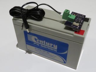
Designs based on the Texas Instrument’s bq24650 Synchronous Switch-Mode Battery Charge Controller for Solar Power With Maximum Power Point Tracking are commonplace on Aliexpress, ebay and Amazon.
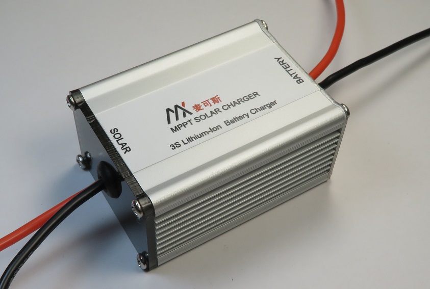
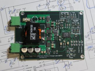
Consumers can purchase assembled PCBs, such as the one pictured above, or complete product enclosed in a relatively nice aluminium extruded housing.
According to the silkscreen of versions pictured on-line, different variants are available including:
- 3S Li-Ion
- 4S Li-Ion
- 4S LiFePo4
- 12V Lead Acid
I’m still old-school and wanted to purchase a 12V lead acid version, but couldn’t find any available for sale.
And like many similar electronics products from the above mentioned on-line retailers, documentation can be sparse.
As the product appeared to have a very well laid out printed circuit board, I decided to purchase one to pull apart and modify. In the process, I documented the design below.
Specification
The 5 to 28V input voltage range supports 36 cell solar panels (sometimes known as a ‘12V panel’). These panels are characterised as having an open circuit voltage (VOC) output of approximately 22V and a voltage at maximum power point (VMP) of around 17V.
Two PCB options are available – one supporting an output of 5A and the other supporting 10A.
The BQ24650 supports a battery voltage of 2.1V to 26V. However, as a synchronous buck topology, the input voltage must be higher than the output/battery voltage. As VMP is set as 17.2 volts, the battery voltage must be set under this.
Hence this is the reason why only 3S and 4S options exist. Lithium Ion chemistry has the highest cell voltage of 4.2V thus a 4S pack will have a maximum voltage of 16.8V – just squeezing in under the 17.2V max.
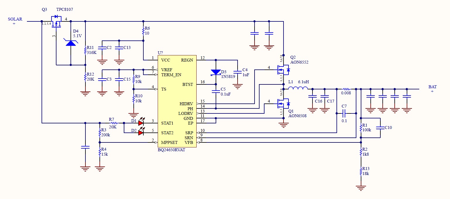
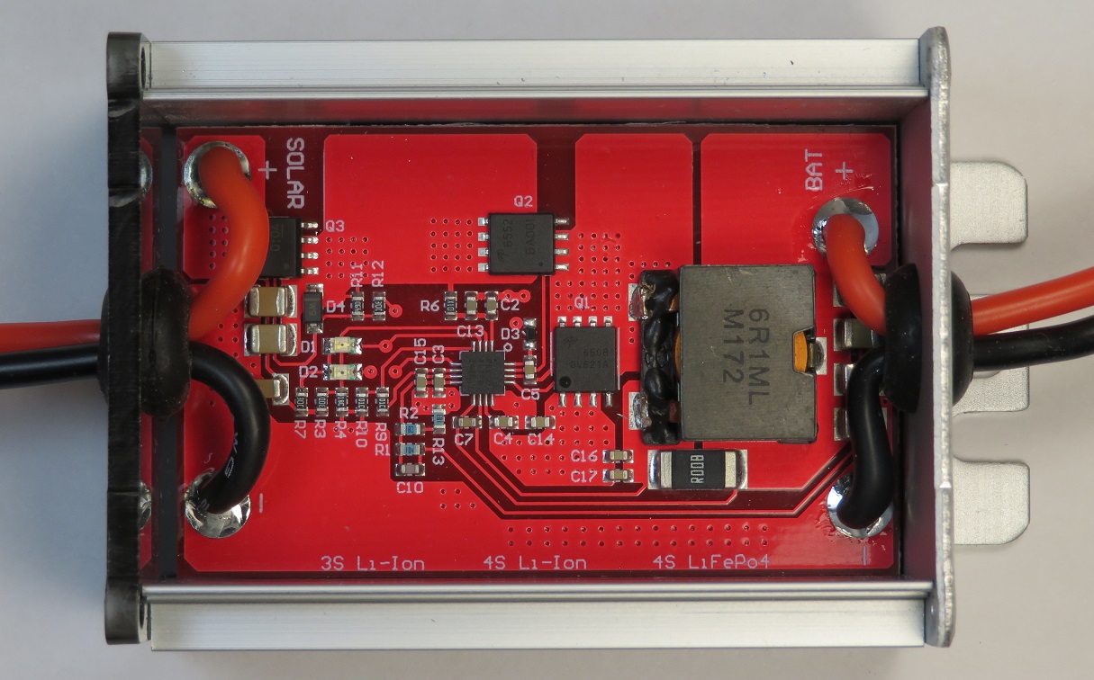
PCB Design & Schematics
The good news is the PCB designators closely follow the designators used in the Texas Instruments datasheet. Where extra components have been added, they have been given an incremental designator following the last designator used in the datasheet. This made it easier to find the MPPSET and output voltage dividers.
MPPSET – Maximum Power Point Set Point
The BQ24650 doesn’t track the maximum power point like more sophisticated designs. Instead, it tries to maintain a constant voltage – the Maximum Power Point (MPP), preset via R3/R4. The BQ24650 will reduce the charge current to try to maintain the maximum power point.
VMPPSET is equal to 1.2V x [1 + R3/R4].
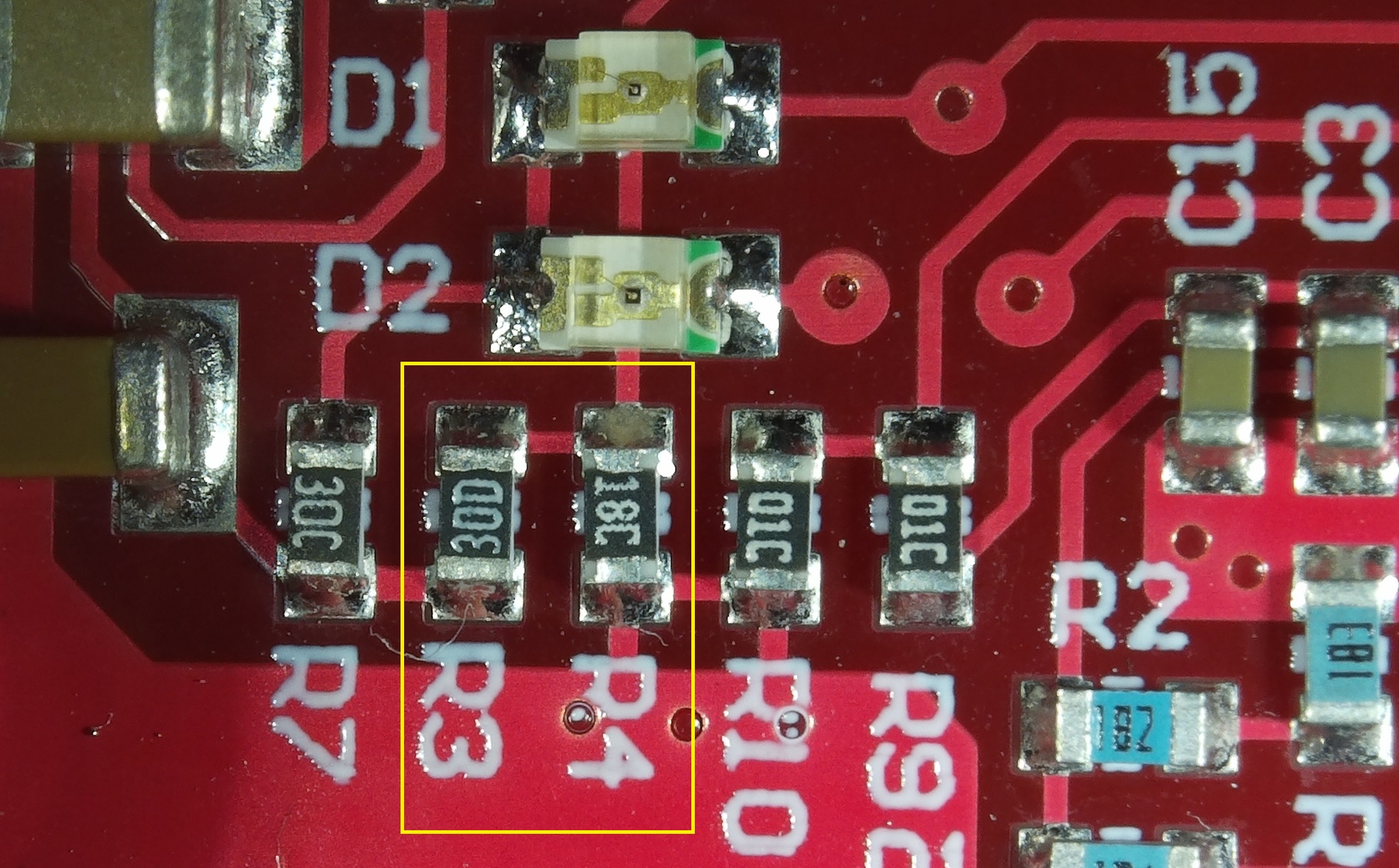
The board has a 200k resistor fitted for R3 (code 30D) and a 15k resistor (code 18C) fitted for R4. This sets the MPP voltage at 17.2V which should be reasonably close for most 36 cell solar panels.
Output Current
The output current is set via RSR , an 8 milliohm shunt resistor. The maximum charge current is set via:
ICHARGE = 40mV / RSR
This sets the current at 5A. This same shunt resistor also sets the termination current to 1/10 of 500mA. Once the voltage reaches the target and the current falls to below 500mA, charging will complete.
Output Voltage
R1 and R2 are used to set the output/battery voltage as per the datasheet, however their positions are swapped. To help cost down, a third resistor R13 has been added in series with R2 to allow for cheaper and more common E24 series resistors to be used.
The battery voltage can be set using:
VBAT = 2.1V x [1 + R1/(R2+R13)]
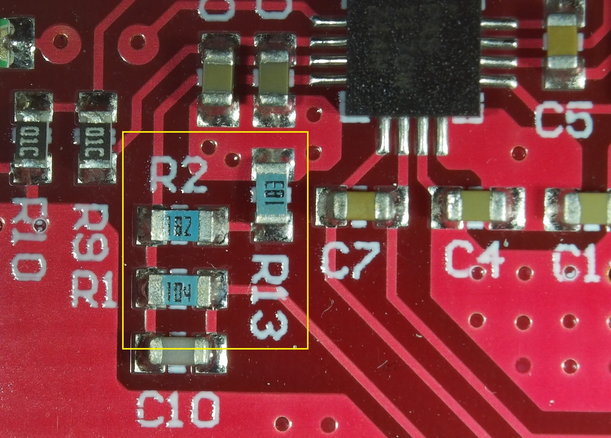
Pictured is a board populated for 3S Li-Ion.
| 3S Li-Ion | 4S Li-Ion | 4S LiFePO4 | 12V SLA | |
| R1 | 100k | 97k6 | 100k | 100k |
| R2 | 1k8 | 7k87 | 15k | 2k |
| R13 | 18k | 6k04 | 2k | 16k |
| Battery Voltage | 12.7V | 16.8V | 14.5V | 13.8V |
Status LEDs
The board includes two LEDs – A red D1 and a green D2. These LEDs report the status of the charger:
| Status | RED (D1) | GREEN (D2) |
| Charging | ON | OFF |
| Charge complete | OFF | ON |
| Charge suspended, overvoltage detected, sleep mode, battery absent | OFF | OFF |
General
The charger can be powered by either the solar panel/input or via the battery – the body diode of the high side FET will conduct, effectively connecting the battery to VCC.
However, the voltage on VCC must exceed the under-voltage lockout of 3.86V and the voltage on VCC must exceed the voltage present on SRN (connected to the battery) before charging will initiate.
If the voltage on VCC is under SRN, the device will enter Sleep mode (<15uA) to prevent draining the battery.
Mechanical
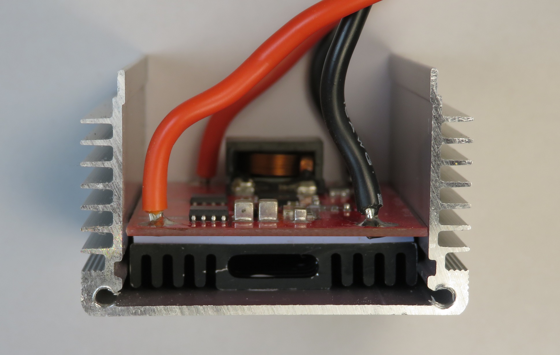
Summary
This cheap and popular BQ24650 based battery charger is a relatively well designed and extensible charger. The output voltage can be reconfigured by changing R1/R2/R13.
Hey there. Thanks for posting all of this detailed info. I got the LiFePO4 version — here are my resistor values:
R1 – 01D = 100k 1%
R2 – 18C = 15k 1%
R13 – 30B = 2k 1%
Even though my R3 and R4 values are as you state in this article, this unit seems to be holding my panel voltage around 20v. I don’t know if I got a bad unit or what. Further investigation is needed.
Rex,
Thanks for the information. I’ve just updated the table.
The MPP voltage will only be achieved if you have a significant load on your panel, i.e. you are putting a couple of amps into your battery. As the battery gets closer to 100% state of charge, it will pull less current, and hence your MPP voltage will rise.
What happens if you put a flat battery on your MPPT? Does the input/panel voltage hover around 17.2V?
Indeed. I discharged my battery, creating more of a load, and got panel voltage holding around 17.2 +/- 0.2v.
I also changed R13 to 1.5k, bringing the bat voltage set point up a bit (about 14.8v). This also increased the charging rate, and made balancing possible with my BMS. I think if I build a bigger battery pack, I may see it draw even more power.
Anyway, I’m now fairly happy with the output of this unit.
Thanks for the great in-depth review ! I was looking for something to use as a charge controller for a 3S or 4S-powered 1kWh portable per power bank. I’m not too familiar with MPPT electrical characteristics, but was wondering if a device like this could be used with a standard power source ? The idea would be either connect 12V automotive (11V-14V) or 12V wall wart supply DC source to input. If using 4S I’d assume a boost converter prestage would be necessary to 17.2V, but otherwise same idea.
Before finding this, my only other option seems to source 1) boost converter, 2) CC/CV DC/DC converter, 3) Li-Ion battery protection board. The auto-sleep and management aspect of this unit seems like it would simplify considerably, especially if I could run just this board of i decided 3S pack Voltage would be sufficient.
Again, thanks for the detailed review !
Thank for review, really helpful. So, if I want to charge a lead acid battery I should buy the 3S Li-Ion version (since lead acid version is nowhere to find) and then shorting the R2 (1k8) I should get a total resistance of R2+R13 = 18k, which is the same as lead acid version.
i am using 4S Li-ion please let us now resistor values VMMPT set and Vbat values
Hi, Thanks for the review.
I am looking into this module to charge a 12V 3ah 4S LiFePo4 battery with a small 6-10W solar panel.
The potential problem I see is that a 6W panel would be producing 300mA which is under the 500mA mentioned in the review.
Am I right to think that if the panel produces less than 500mA it wont be able to charge the battery using this controller?
If so are there other alternatives?
Thanks
Thanks for the Review,
I found it after checking this on my own. But I found a little mistake in your schematic.
The package of Q3 is wrong.
D4 is connected to the gate of Q3 and R12 is connected to STAT1. I think this should switch on Q3 while only while charging.
I hope you agree. If you could change it the review would be perfect.
Sorry I made also a mistake D4 is ok. But R12 is not connected to ground.
Yeah it make sense because the circuit like in the schematic is useless, the transistor is always switched on when there is voltage on the battery side…
Hi, I have a 4S Li-ion, here are the values:
– R1: 96C (97.6kΩ)
– R2: 87B (7.87kΩ)
– R13: 76B (6.04kΩ)
Which makes Vbat = 16.83V
Excellent article, it was very helpful in my research for a simple MPPT controller for my 12V 30W solar panel and 4S2P battery pack.
can we get parameters for 25V battery charging ?
Hi, I’m thinking about real MPPT Tracking – I mean remove R3/R4 and provide reference voltage form microcontroller. Microcontroller will be connected to PV input – measuring current and voltage then using Disturb and Observe or other smart algorithm will run real tracking. What are you think about that idea?
How do i set the mmp right with resistors?
usually people buy these controllers to match up with their solar panel..
If mine has a unloaded voltage of 19V and is 10W how do i “set” the mmp that the manufacturere maybe gave me with 17V?
Or if you don’t know the mppt voltage how to work with this pcb?
my 4S Version:
R1 96C 97,6k, R2 76B 6,04k, R3 30D 200k, R4 18C 15k, R13 87B 7,87k
V_MppSet= 17,2V
V_Bat= 16,83V
Hello,
Thanks for the article, I have a question about this charger,
If I want to connect a Load that will drain the battery while charging on this charger, how should I do ?
Many thanks
Bruno
Bruno,
You can simply connect the load directly to the battery. It won’t effect the charging cycle.
Connecting a load directly to the battery means you have no low voltage disconnect (LVD) protection. You may want to investigate options for LVD.
Hey, what do you think is the maximum solar panel wattage I can attach to?
Tom, if you have a 12V battery, I would be thinking about 60W. Having a larger panel won’t harm it, provided you observe the maximum input voltage of 28V (i.e. you will need to use 36 cell ’12V panels’).
What’s the best wiring combination and output voltage using 10 solar panels of 300 watts each? This will feed a 24-volt system with an MPPT controller of 60 amps.
I was wondering if there are any new versions of this chip available. I’m putting a small setup together for my astronomy equipment, but am unable to locate the LiFePO4 with aluminum housing. The 3s is available with the housing on Amazon for $9 right now and I’m sceptical the 4s will fit. I’m sure I can come up with a cooling strategy, but thought I would check to see if there’s anything new available and how everyone’s setups have lasted. Thank you for any help you can provide.
Hi All, i have implemented the smae circuitry for 7.4V 20.8Ah battery, keeping set voltage as per the battery voltage my question is that do we have to ground the TERM_EN pin or just have to keep it short with Vref?
Secondly, input given is 24 V 6.5Amp, but my circuitry consumes hardly 300mA, so does it will affect charging current too??
permanently wiring the solar input can be double checked for correct polarity so needs no reverse polarity protection. Is the output reverse polarity protected? or does it need a fuse for reverse polarity protection?