
Cheap Lithium Battery “Active Balancer” boards have been turning up on Aliexpress and other eCommerce sites.
But there has been some scepticism if they are genuinely active balancing and quite a few conflicting forum posts. Some have even claimed the ‘1R0’ inductors are actually 1 ohm resistors.
The more traditional passive balancer boards will simply dump any excessive charge into a resistor, wasting this energy. For example, if the maximum voltage threshold was set at 4.2V, once the cell’s terminal voltage exceeded 4.2V, any excess charge would be dumped into a resistor and dissipated as heat until the terminal voltage fell below 4.2V.
Active balancer boards are designed to divert excess energy from the cells with the highest voltage into cells that still require charge.
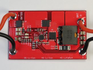
To find out how these cheap boards work, I jumped in and paid $8.26 USD for a 3S version from the Aliexpress Dykbhuang Store.
This board has a PCB part number of JW-3S1.2A V3.0. By decoding the part number, the designer appears to have the initials JW. This is a 3S version 3.0 PCB with a maximum balancing capability of 1.2A.
ETA3000 Inductive Cell Balancer IC.
The easiest way to understand how they work would be to ascertain the actual integrated circuit (I.C.) used in the design and have a study of the datasheet. The board was conformal coated, but scratching off the coating reveal a marking of GS9q.
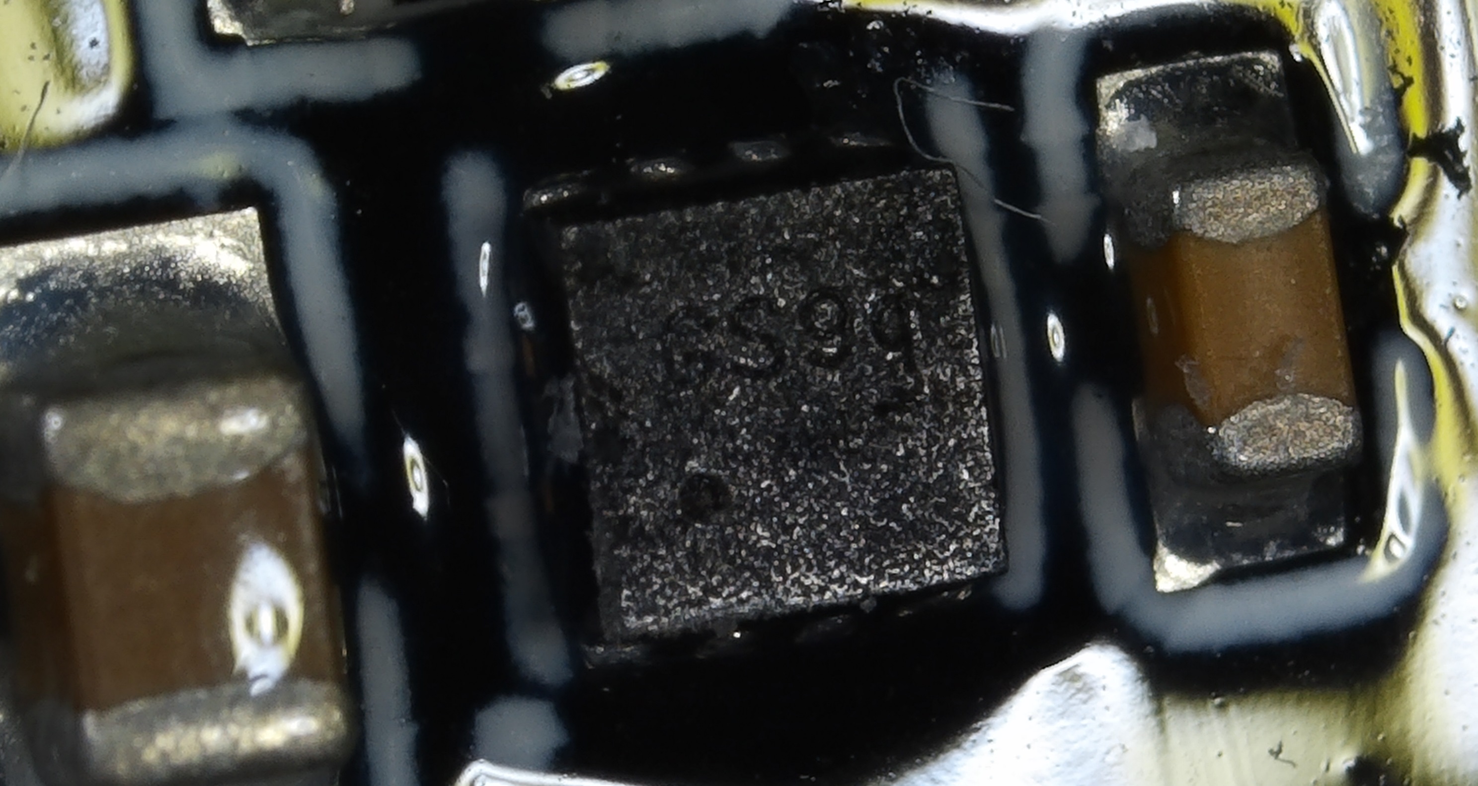
After quite a bit of searching, I would come to the conclusion that it is a ETA3000 Inductive Cell Balancer IC from Shanghai manufacturer ETA Solutions.
The part doesn’t seem to be listed on their website, but the datasheet can be found here, thanks to Google.
This device comes in two packages, a SOT23-6 or DFN.
The DFN version, part number ETA3000D2I has a marking GSYW where it appears the Y is the Year and W is the week. This would suggest my parts were made in 2019, but I’m uncertain about the week datecode.
Schematic
The ETA solutions datasheet provides the typical circuit:
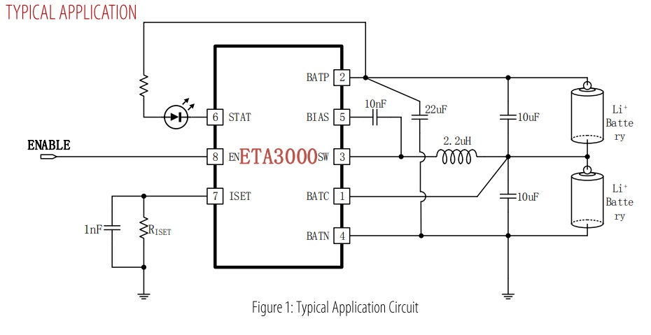
According to the datasheet, the “ETA3000 is a battery cell balancer with lossless inductive architecture based on ETA’s proprietary technology.”
The device will shuffle current between the two cells until the cells are balanced. To do this, it uses an inductor switching at 1MHz. (The 1R0 marking means the SMD inductor is 1uH)
To begin the “shuffle”, the cells must exceed the unbalanced detection threshold of 100mV and be within the Under-Voltage Lockout (UVLO) and Over-Voltage Protection (OVP) thresholds. This is between 3.75 and 5V.
The balancing will terminate when the cells are balanced. Balance accuracy is specified as +/-30mV.
When not balancing the device goes to sleep. Sleep current is specified as 2uA.
Layout
The layout is consistent with the recommendation from ETA solutions. The 10nF bootstrap cap has been placed on the left hand side of the ETA3000.
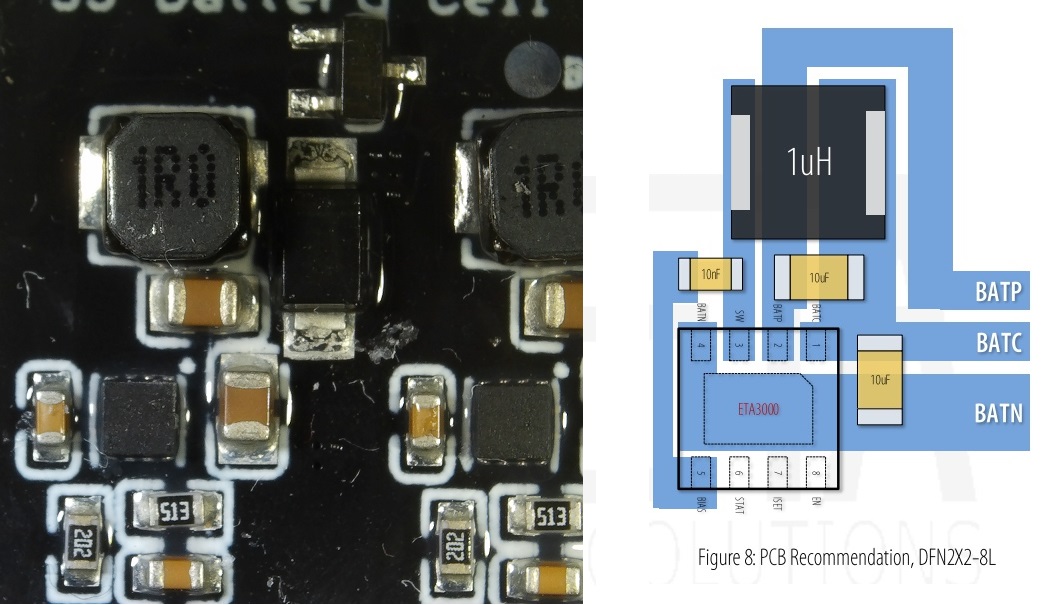
The 51k resistor (513) and 1nF capacitor below forms the programmable current setting. The 51k sets the maximum current to just short of 1A. (My Aliexpress listing said 1.2A in the title, and 1.5A in the description/features)
One would assume the 2k resistor close to the STAT pin is the LED current limiting resistor.
Multicell Balancing
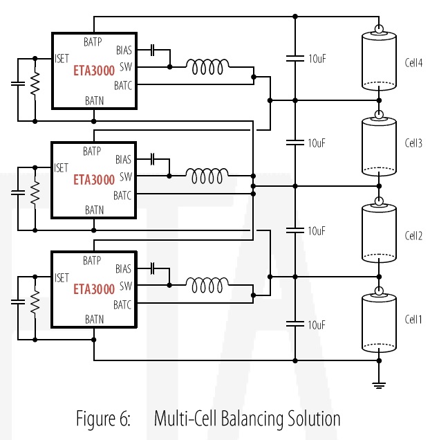
The topology allows overlapping ETA3000 to be connected together to balance multiple cell battery packs. Merchants on Aliexpress are currently selling boards for battery packs from 3S to 16S.
Maximum transfer efficiency is specified at up to 92% per device. Charge has to be passed though sequential cells, but one could argue this is still more efficient than wasting all the energy in heat via a resistor.
It should be noted, the balancing accuracy of +/-30mV is between the two cells connected to a single ETA3000 and not over the entire board.
In a worse case scenario, it is possible for these errors to accumulate between cells of the pack. For example, the first cell could be 4.10V, the next cell 4.07V, then 4.04V etc.
However battery packs should be made of identical and matched cells that rarely need balancing, assuming they are not abused – i.e. depleted beyond their low cutoff voltages. Hence, only one or two cells in a pack should ever need balancing.
Extra Protection Circuitry
In addition to the typical circuit, extra protection has been added to this design. (Thanks JW)
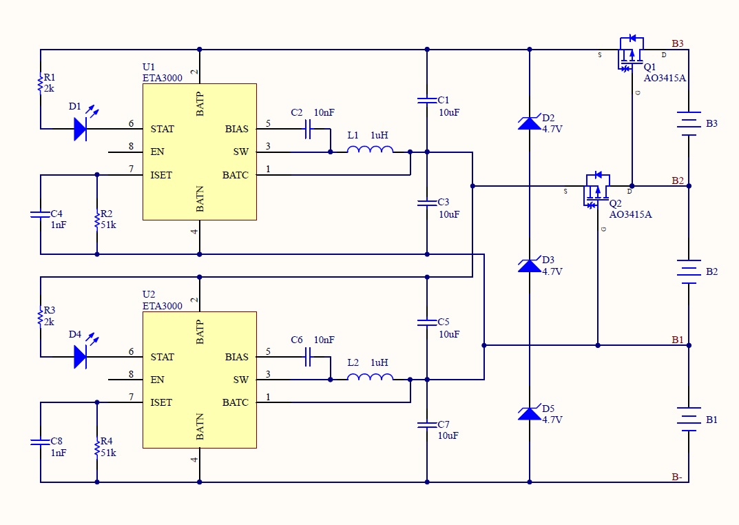
The large diodes on the PCB appears to be a 4.7V 1W Zener and is designed to provide some protection for when a cell voltage exceeds the breakdown/knee voltage. I say “some” protection assuming cell taps are fused and not low impedance connections straight into the battery.
The SOT-23 parts also forms as added protection. They are AO3415 20V P-Channel MOSFET (marking AF9TF J) and provides reverse voltage protection on cell taps B2 & B3 (on my 3S V3.0 board).
I have yet to work out why cell tap B1 is not reverse voltage protected. While this input does not power either ETA3000 (the chip is powered via BATP), the datasheet does indicate the absolute maximum rating of BATC to BATN is -0.3V to 6V, suggesting the BATC pin is not tolerant to reverse voltages.
Testing
The desktop study would suggest the board is the real deal. However to date, I have only done very preliminary testing.
The Lithium Battery Active Equalizer Balancer Energy Transfer Board comes complete with cable to bare-ends. Please note, this connector is not a JST-HX balance connector that you would commonly find on hobby packs.
I have wired it to a 18650 battery holder so I can switch in and out batteries of various states of charge.
So far the board has successfully balanced the batteries to within 30mV between adjacent cells.
More comprehensive testing is to come ….
It will be perfect if it has balance between first and last cell.
This is Possible if you add another Chip betwen the first and the last cell.
But then you must add a Subtract-Component between last and second cell so the voltage is right.
Thank you, your explanation of this device was exactly what I needed to find and I look forward to seeing results. Whilst looking for reviews of the product you tested I found this product that looks potentially better still if it performs as claimed, would be very interested in your views on it https://rover.ebay.com/rover/0/0/0?mpre=https%3A%2F%2Fwww.ebay.com%2Fulk%2Fitm%2F322720419453
Have you successful received the chips?
Great thanks!
I found the chips on Taoboa. Going to purchase them through Superbuy.
https://item.taobao.com/item.htm?spm=2013.1.20141001.1.38b23e2bROniY2&id=574254010963&scm=1007.12144.95220.42296_0_0&pvid=98bc1cbe-81c0-4d91-8f92-73426566fe1d&utparam=%7B%22x_hestia_source%22%3A%2242296%22%2C%22x_object_type%22%3A%22item%22%2C%22x_mt%22%3A0%2C%22x_src%22%3A%2242296%22%2C%22x_pos%22%3A1%2C%22x_pvid%22%3A%2298bc1cbe-81c0-4d91-8f92-73426566fe1d%22%2C%22x_object_id%22%3A574254010963%7D
Did the chips arrive~
Thank you for this article. Looks like a usefull board. Do you know what do the fets do ? It seems like they would normally be on since the gate is a cell voltage below the source. But even if it is off the body diode will be forward biased. I’m not a hardware guy so I may be missing something. Do the inductors just convert the current to a magnetic field. I would only think that would work if the current was chopped so that it didn’t look like a dc current.
Really nice review! Looking forward to further tests!
Thanks for this article. It is very useful.
Could this be adapted to work with supercapacitor voltage ranges? Like between 1v and 2.7v? From the datasheet I couldn’t really find a minimum voltage, it looks like input ranges depending on the pin is .3-12v or .3-6v. That makes me think the ETA3000 might work for a supercapacitor active balance.
Hello! Friend, I have a question. If I change the current-sensing resistor from 51 kOhm to 25 kOhm, will I get the value of the balancing current 2A, as indicated in the datasheet, or do I also need to replace the inductor and capacitance with a more powerful one? I am building a motorcycle battery on LiFePo4, and the charging current of the motorcycle generator is quite high to make 3.9 volts on one cell, when on the other three only 3.5-3.6V. If this cell is the first or last in the circuit, the current strength is not enough to transfer energy to the next cell. Thanks.
While the datasheet for the ETA3000 indicates it can do up to 2A, we don’t know the specifics of what inductor has been used (outside of the value).
Hi:
Arn`t C3 and C5 just connected in parallel? I have built a few circuits (not the exact schematic shown) and the leds only flash. Anyone else have this happen?
Tom
Has anyone built this circuit and it works?
Tom, You can purchase the boards cheap on Aliexpress. Why do you want to build one? I assume it will cost more in parts.
Hi Sam:
Actually, it is possible to build the circuit for less than what it costs on AliExpress or ebay (not a big savings when including the PCB). Besides, I`ve designed a Li-ion protection board and wanted to add the balancing directly on that board. I have gotten the circuit to work but the ETA3000 board MUST be laid out exactly as the eta3000 manufacturer specifies, I made some slight deviations and it did not work. Also, for the board analyzed here the filter caps are about 2.2uf, not 10uf, I removed the caps from the board and checked them.
There is anybody that used this kind of Active Equalizer Balancer:
https://www.aliexpress.com/item/4000110143557.html
Or this kind:
https://www.ebay.ca/itm/5A-Balancer-4-LTO-LiFePo4-Li-ion-Battery-Active-Equalizer-Balancer-3S-16S-17S/293403482737?ssPageName=STRK%3AMEBIDX%3AIT&var=592235997181&_trksid=p2057872.m2749.l2649
Thank you!
So, what’s the bottom line for this board ? Still satisfied as to how it works ?
Are the state LEDs lighting up when the cell is full (not balanced) or the contrary ? Do you think they will draw a lot of amps from the cells and need to be desoldered from the board ?
Thank you for this great article !
The board I have is somewhat different but it also has JW as the first part of the name. I got my board from this aliexpress seller. https://www.aliexpress.com/item/4000241881122.html?spm=a2g0s.9042311.0.0.27424c4d9B4LmV . I cooked a couple of resistors and I am trying to find out from other users what value they are supposed to be so I can replace them. Boxes #1 and 2 identify the locations of the resistors. https://docs.google.com/drawings/d/1YWpyMI6JCmRUIyEDDVjgbKz_qYptcoCwIbkwdVqp-QA/edit?usp=sharing. I will be posting my research on endless-sphere.com .
You state it in your review but nobody seems to have caught that a LiFePO4 cell does not make it to 3.75v so the balancer with a 3.75vdc lower limit will not work for LiFePO4 batteries. Lot of false advertizing out there.
3.75v would be appropriate for LiPo batteries that operate in 3.75v to 4.2v range.
I noticed that in the write up too. The range mentioned looks appropriate for LiIon but not LFP. I can tell you though that I also purchased these from AliExpress in several different denominations from 4S to 16S and they also work with LFP. The caveat is that the balance capability does seem to be limited to about 30 mv. On the plus side the device works diligently to achieve the achieve 30 mv delta. just not necessarily across the entire pack. The same device seems to work the same way on LiIon and even LTO if I’m doing it right. Another peeve I have is that it doesn’t become active until the delta reaches 100 mv. I have not deconstructed any to see if the components conform to the application notes. Does that help?
Thanks Craig for going to the trouble of doing the write-up.
I must admit I either don’t understand or don’t see the point in the “added protection” schematic.
I just received a 3S model, PCB is marked “3S NCM/LFP Battery balancing V1.1”
Haven’t done very extensive testing, linking it to half charged unbalanced Li-ion batteries it starts balancing immediately on both balance circuit.
The PCB gets quite warm although nowhere near worrying temperatures.
LED’s come on when a balancing circuit is active, balance ends with adjacent cell voltages within 50mV of each other, end to end are about 100mV unbalanced.
During charging with bench power supply set at 12.4V / 1A, one balance circuit active, switching frequency is 1.4MHz, inductor ringing at 32MHz.
I didn’t note the switching noise levels but they were quite low.
For some reason the balancing seemed to have given-up at the end of my charge test: The top cell had hit 4.22V while the other two were at 4.09V top balance circuit was inactive while top cell was being overcharged.
I’ll have to look into that deeper…
What is the point of balancing cells AFTER they are charged?
Surely there is a module that balances WHILST charging?
I suspect this module can be connected and balancing whilst charging, BUT it does not perform the most important role of LIMITING charge voltage or current.
Can you suggest a module, chip, or schematic that can do all these roles?
Thanks for the great article.
I have several of these and had been wondering what the differential trip voltage was.
100 mv is in line with what I am seeing.
Thanks again. Much more here for me to read up on
Balancing works well, but the current draw after balance is finished is higher than expected and discharges the cells in 8 days. Pulses every 2 seconds to check state, 2uA in sleep, 700 uA during check at 7 msec. Average is 4.4 uA, theoretically, but is much higher at 60 mA for some reason.
Each IC is a bi-directional buck switcher between two adjacent cells. It measures the pair of cells on one IC and decides direction to buck transfer from higher voltage cell to lower voltage cell. The multiple circuits are cell overlapped so it can leap-frog charge transfer up or down the stack of cells.
There appears to be a stability issue. Sometimes it works, sometimes it does not.
The multiple IC’s do not appear to have any syncronization timing in their measure/pump cycles so a given cell voltage measurement cycle can get corrupted by the charge pumping of adjacent IC overlap circuit. This can cause a wrong decision on pump direction.
I think the circuit would work great if there was a common cycle synchronization between the IC’s. As presently designed they are unreliable.
Very tinteresting
Noob question here. What is the best way to charge the 3S batteries? I have a bench power supply where I can set the correct voltage and current or should I use a special charger? On the supply I might have to decrease the current over time and can guess a 3S automatically does this.
Hello, thanks for the work.
I want to enable/disable the board with a switch.
Does someone know an easy solution to pull the EN pin of all ETA3000 high/low by a switch?