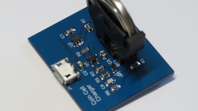
This design is intended to recharge Maxell ML2032 Lithium Manganese Dioxide rechargeable coin cell batteries with a nominal voltage of 3.0V. These are ‘special’ coin cell batteries designed specifically as a rechargeable secondary cell.
It is not recommended to attempt to recharge a primary CR2032. These cells have not be designed for recharging.
Background
Rechargeable replacements of the popular CR2032 3V lithium coin cell battery exist, but one caveat is reduced capacity. The common CR2032 from name brand manufacturers such as Panasonic will have a capacity of approximately 220mAh.
Rechargeable replacements of the CR2032 appear to come in a range of different chemistries.
Maxell (ML2032) and Renata manufacture secondary Lithium Manganese Dioxide with a nominal voltage of 3.0V and a capacity of approximately 65mAh. These cells require a constant charging voltage of 3.1V.
Renata manufacture an ICR2032 60mAh Lithium cobalt oxide cell with a nominal voltage of 3.7V. Also in their portfolio is a IFR2032 45mAh Lithium iron phosphate with a nominal voltage of 3.2V
Also commonly available is the LIR2032 coin cell batteries, with LIR standing for Lithium Ion Rechargeable. As you can guess these behave like Lithium Ion cells and have a nominal voltage of 3.6V and a capacity of around 40mAh.
Each different chemistry has specific charging requirements and are not interchangeable.
Circuit Design
Maxell, Panasonic and Renata provide consistent example circuits and guidelines for charging Lithium Manganese Dioxide coin cells.
This typically consist of either a 3.1V or 3.2V regulator, a diode and a current limiting resistor. The regulator provides the CV and ensures no more than the absolute maximum 3.3V is applied to the cell during charging. The diode prevents current feeding the regulator if the input power supply is removed.
The current limiting resistor ensures the charging current never exceeds the maximum permitted for the battery. For the ML2032, this is 2mA – yes, another caveat. With a capacity of 65mAh, charging time is only thirty two and a half hours – assuming a constant current charge, something this circuit does not provide.
To calculate the resistor value, it makes the assumption the cell could be discharged to a minimum of 2V. With a 2mA maximum charging rate, this means our resistor must be greater than 550 ohms when charging from a 3.1V regulator.
The non-common voltage requires the use of an adjustable low drop-out voltage regulator. In this design the LP2980 was selected from Texas Instruments. This LDO can provide an output current up to 50mA and comes equipped with an enable pin.
As an optional extra, this design features a TPS3700 windowing comparator. It can be used to enable charging when the battery voltage is within an acceptable window of 2.0V to 3.0V.
This can also be used to terminate the charge when the battery exceeds 3.0V. A LED connected to the regulator’s output will extinguish once the battery terminal voltage reaches 3.0V, indicating the battery is charged.
The comparator and associated passives can be omitted, but please ensure R2 is populated to enable the regulator.
Design Files
Design files can be downloaded from the Circuit Maker website. Circuit Maker is a free EDA tool from Altium.

Be the first to comment