

I’ve been wanting to automate my EV (Electric Vehicle) charging.
It’s a long story for another day. I had started out with a high level RS485 interface into my EVSE (Electric Vehicle Supply Equipment) and hit some ‘bugs’. A month later, it turned out much easier to fall back to KISS principals (Keep it Simple, Stupid) and directly turn on and off the power when I needed too.
While my EVSE is currently set to charge at a paltry 10 amps, I wanted something a little more robust than a cheap ESP8266 based Smart Plug adapter. Designed to a price point, many of these smart plug devices are fitted with relays with dubious current ratings. I’m familiar of stories where such devices have failed within hours on the most straightforward resistive loads such as a 2400W heater, only to be replaced under warranty and fail again, shortly after.
For me, it made sense to build a device that could drive an off-the-shelf contactor. I could then select a suitably rated and standards approved contactor for the task. Most contactors are designed to be mounted on an industry standard DIN rail, hence it was only logical to design my device into a DIN rail enclosure to sit long side it.
Camden Boss made just the enclosure – the CNMB/2/2 light grey UL94-V0 flame retardant polycarbonate DIN rail module box.

Most industrial rated contactors have coils that operate from standard mains voltages – either 230V/120V or a lower voltage 24VAC/DC. (Some are 12V, but most safety extra low voltage ‘safety loops’ operate at 24V).
Low voltage 24VDC DIN rail power supplies are a dime a dozen and from a compliance point-of-view a coil supply of 24V made sense. This means the ESP32 module is all low voltage and the mains rated power supply is also standards approved.
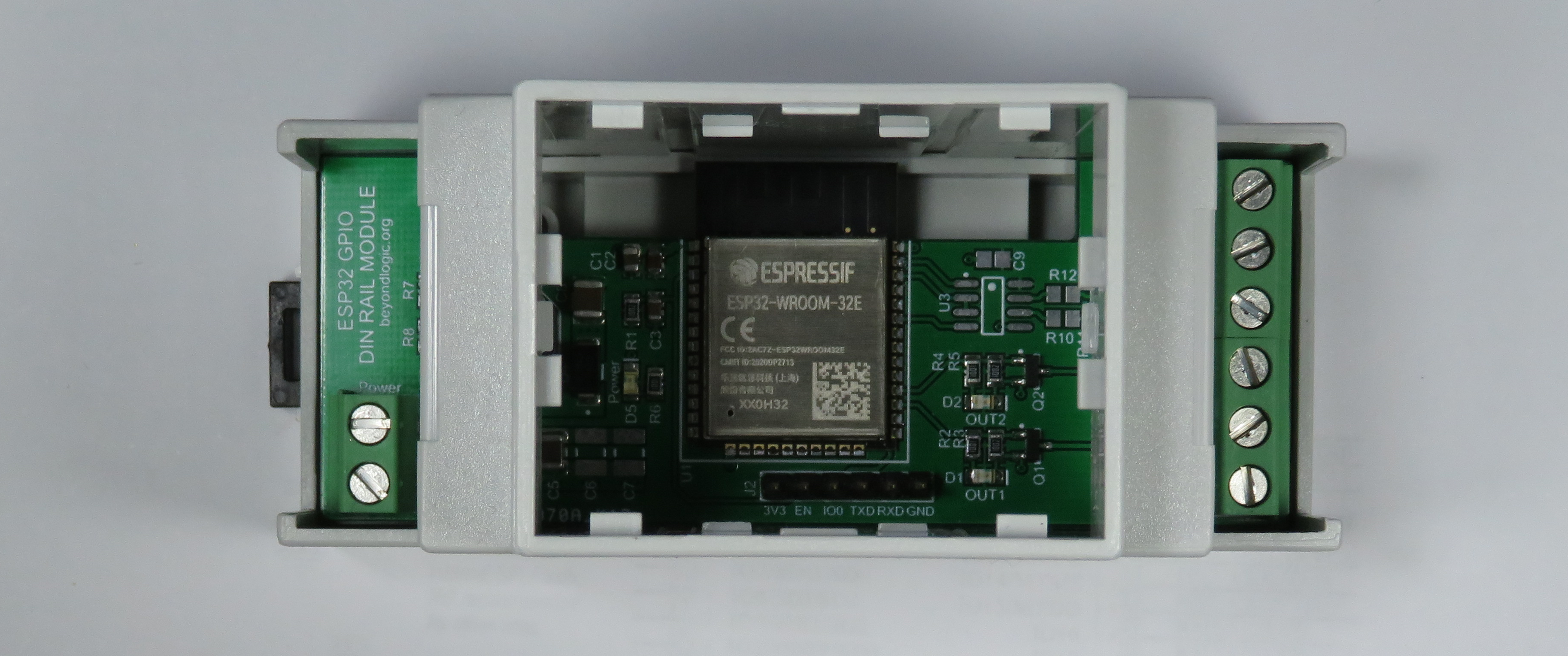
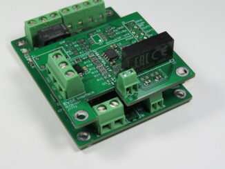
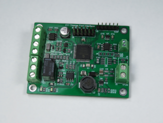
PCB Details
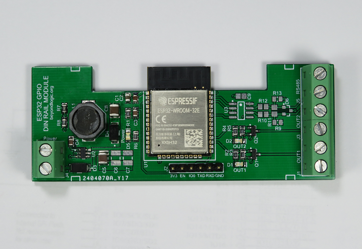
The ESP32 DIN rail module consists simply of an ESP32 WiFi/BLE MCU, two small MOSFETs to switch the contactors on (one spare), an optional RS-485 interface and a DC-DC Switchmode power supply.
The LMR16006 DC-DC converter fitted is rated for a maximum input voltage of 60V and supplies power to the 3.3 volt ESP32 and 485 interface. This allows the module to operate from approximately 5 to almost 60 volts. (A cheaper LMR14006 can also be used with a maximum input voltage of 40V)
The two MOSFETS are rated for 60V VGS and are configured as a low side switch. The positive terminal of the contactor coil is wired directly to the DC supply input of the module. Hence, the contactor output supply is determined by the input supply voltage.
The optional RS-485 interface is based on the 3.3V THVD1410 RS-485 Transceiver and can be loaded if required.
Design Files
Design files can be downloaded from the Circuit Maker website. Circuit Maker is a free EDA tool from Altium.
- Open in Altium 365
- ESP32 DIN Rail Module version 1.A.2 Gerbers – PCB (Zip)
- ESP32 DIN Rail Module version 1.A.2 Schematics (PDF)
- ESP32 DIN Rail Module version 1.A.2 Bill of Materials (XLSX)
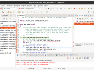
Firmware
Firmware for this design can consist of write-your-own, or off-the-shelf.
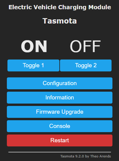
Tasmota is a popular open source firmware for ESP8266 devices (RGB light bulbs, Smart plugs etc) and comes with an ESP32 port. While still in Beta, I used Tasmota to test this board without any issue.
Tasmota is highly flexible and allows control via MQTT, WebUI, HTTP and serial. It includes support for timers, rules and scripts. Depending upon your task, you can make the decisions on the device or push them down via MQTT as part of a broader home automation system.
The timer functions can be useful in implementing basic charging during Time of Use (ToU) tariffs. For example, my local electricity distribution service provider, SA Power Networks offers a cheap ‘Solar Sponge’ network tariff between 10am and 3pm daily. They also offer an Off-Peak network tariff between 1am and 6pm.
Tasmota will require configuration of the GPIO. Output one and two are connected to GPIO16 and GPIO17 respectively. These should be configured as Relay outputs. Alternatively, you can use the template below:
{"NAME":"Electric Vehicle Charging","GPIO":[0,0,0,0,0,0,0,0,0,0,0,0,224,225,0,0,0,0,0,0,0,0,0,0,0,0,0,0,0,0,0,0,0,0,0,0],"FLAG":0,"BASE":1}
My end goal is to write my own firmware and make standalone decisions on the device (based on electricity price). The beginning’s of this firmware can be found at:
https://github.com/craigpeacock/ESP32_DINTimeSwitch
Industrial Enclosure
While the ESP32 DIN Rail Module is a general purpose module and can be used for a variety of tasks, as mentioned in the background my primary motivation was to automate EV charging.
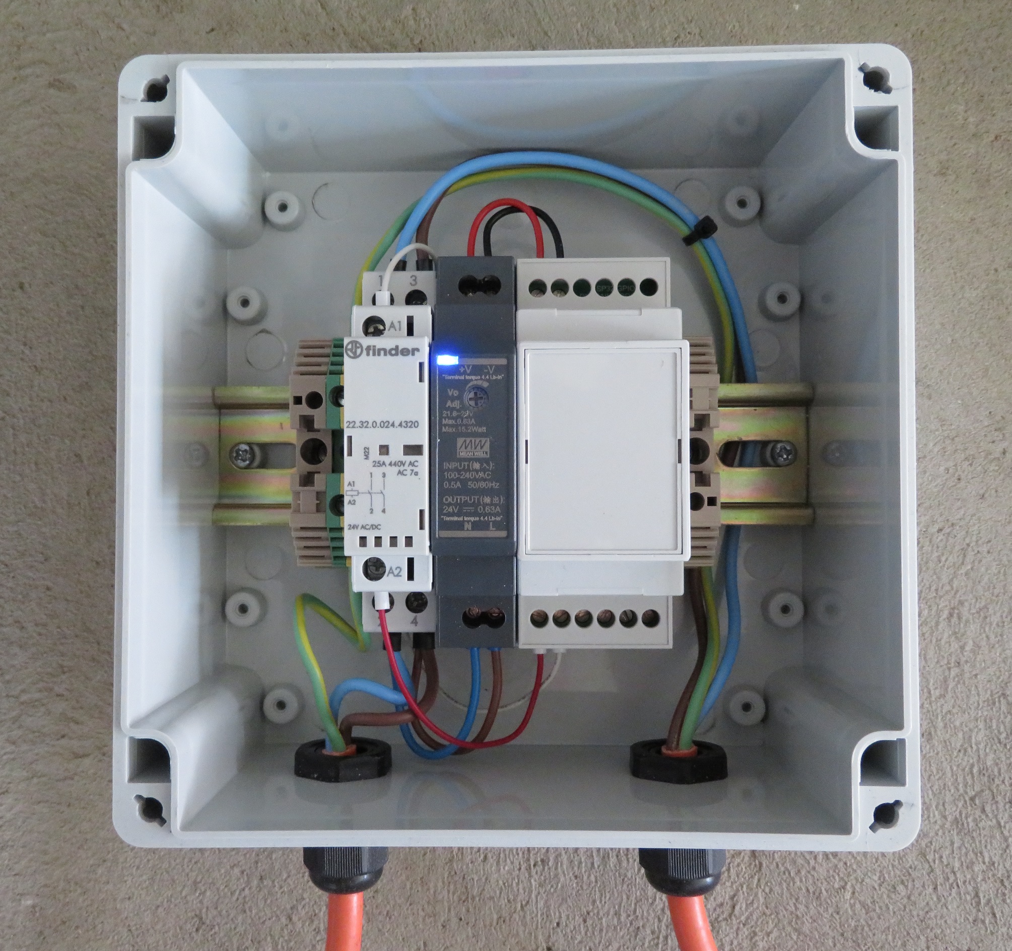
My system consists of a Finder 22.32.0.024.4320 Contactor and a Meanwell HDR-15-24 24V Power Supply mounted into a Allbro ENL161609C enclosure.
The EV appears to have very good power factor > 0.95. The contactor is rated for 25A @ AC1/AC-7a.
Hello Craig, Fantastic Job!
I am from MEAN WELL, and I am pushing our business to the EV charging sector. This explains very well how and why HDR has better sales than the IRM series in terms of the same use.
I am also curious about the real application looks like with your car.
Are these for sale somewhere? Even just the PCB?
Jack, sorry I don’t have these for sale. If you are after just the blank PCB, the gerber files are available above. You can upload these to your favorite board house (http://www.pcbway.com, http://www.jlcpcb.com etc) and get them manufactured.
I would like to make some of these pcb’s and let them be assembled.
Unfortunately there is no CPL (pick and place) file avaiable. Is it possible to add this file to the release files ?
I also need CPL file… thank you very much!
Which terminal-blocks are those on the bottom of the board? They are missing in the parts-list! Nice work! 🙂
Max, looks like the bottom terminal blocks in the BOM are 3x 2-way Phoenix Contact 1729128.
I must have substituted them for 2x 3-way Phoenix Contact 1729131.
Hi Craig, I would like to congrats you for this design. Which company you used to assemble the components and pcb manufacturing?
Dear Craig, well done for your board. Infact I made one but I have problem how to connect the FTDI board to upload the sketch. Do you have a diagram please?