

This device acts as the vehicle when connected to an EVSE (Electric Vehicle Supply Equipment) and negotiates the supply of power.
It can be used in EV (Electric Vehicle) conversions, or in applications where you want to obtain power from public charging infrastructure – i.e., battery trailers to replace dirty and noisy generators, electric watercraft etc.
Both hardware and firmware is provided as open source. The provided firmware will allow the EVCC to successfully request power and obtain the maximum obtainable current. Boiler plate code is available for the CAN interface and some firmware development would be expected to interface it to your charger or battery management system.
Specifications
- Designed to be compatible with IEC61851 Electric Vehicle conductive charging systems and the former SAE J1772 Electric Vehicle Conductive Charge Coupler specification.
- Communication is via Control Pilot (CP) / Proximity (PP).
- Supports locking solenoid (Tested with Duosida DSIEC-EL).
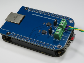
- Based on Microchip dsPIC33EP128GS804 MCU.
- 2x CAN2.0B ports to talk to ECUs (Engine Control Units) such as BMS (Battery Management Systems)/Chargers.
- Includes support for SWCAN used by Tesla destination chargers (work in progress).
- Operates from a wide 6.5 to 40V supply (note: input supply also feeds solenoid via H-Bridge). Recommended supply is 12/24V depending on locking solenoid.
Hardware – Theory of operation
IEC61851/J1772 Interface
Readers should be familiar with IEC61851 / J1772 signalling. If not, please refer to Wikipedia.
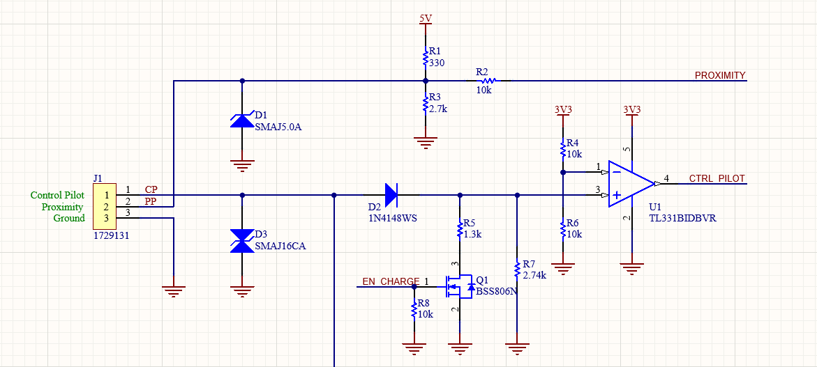
J1 is to be connected to the EVSE via a standard connector, be that a J1772 Type 1 or IEC61851 Type 2.
The EVSE will generate a 1kHz +/-12V signal on the Control Pilot (CP) to indicate availability of power and the maximum current we can pull. The D3 TVS diode provides some protection to our front-end circuit, clamping any stray input voltages to approximately 16V.
Small signal diode D2, Resistor R5 & R7 make up the typical vehicle side interface as per the standard. A load of 2.74k (R7) indicates the vehicle is connected and when the 1.3k resistor is switched in parallel, we are ready for charging (i.e. we request power to be connected).
D2 rectifies the signal, so only the positive going pulse is loaded/attenuated. This provides the EVSE some confidence it is a real car loading the CP and not the connector dropped in a puddle of water.
Finally, we can obtain the maximum current we can draw from the duty cycle of the 1kHz signal. We connect this to a comparator operated from 3.3V to elegantly reduce the voltage and not over-stress the MCU’s I/O pin. The TL331 allows maximum input voltage of 38V irrespective of the supply voltage.
Tesla SWCAN Support
This board also includes experimental support for Tesla SWCAN (Single Wire Controller Area Network) communication. This is optional and does not need to be populated.
Tesla have used SWCAN over the control pilot to digitally communicate between the EVSE and the EV. Some Tesla Destination Chargers only talk ‘Tesla’ mode and this can broaden compatibility to include these chargers.
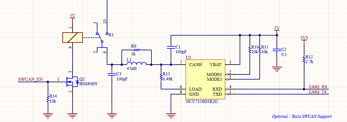
The circuit is based on the investigative work of Damien Maguire. See this thread on the open inverter forum for more information.
It is based on a NCV7356 Single Wire CAN Transceiver and is switched in and out of circuit via a relay (K1). Pin 10 is connected directly to the CP line before the diode to enable unimpeded communication.
Locking Solenoid
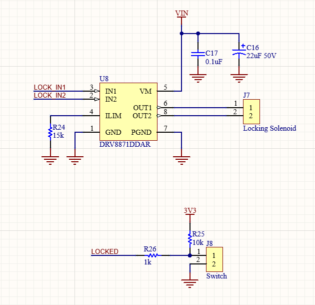
Provision has been included to operate a locking solenoid. Once charging has been enabled, the charge port normally locks preventing the removal of the cable. This prevents the cable being removed while current is flowing, and can also prevent theft of un-tethered cables.
Locking solenoids come in various configurations, but generally consist of a solenoid that inserts and removes a locking pin. When energised for a brief period (< 200mS) the device will lock. Reverse the polarity, energise again, and the device will unlock.
The DRV8871 50V, 3.6A H-bridge motor driver has been selected to control the solenoid. The maximum current is set via R24 connected to the ILIM pin. The part has an exposed thermal pad, however as the device is only active for a very short period, thermal issues are not expected.
The state of the lock can be determined by a digital pin, if the locking switch is wired in to J8.
Dual CAN2.0 Interface
Two external TCAN332 CAN transceivers are included on-board to provide the physical CAN interfaces. As the dsPIC only includes two CAN2.0B controllers, both interfaces are only available provided one controller is not dedicated to the Tesla SWCAN Interface.
120 ohm termination resistors (R20/R21) can be populated if the device is located at the end of a CAN bus.
MCU
This design is based on a Microchip dsPIC dsPIC33EP128GS804-I/PT micro-controller. It was primarily selected, as it contained two CAN2.0B interfaces.
Power Supply
The internal 5V power supply is based on a LMR16006 4V to 60V, 600mA Switching Buck Regulator. This provides a wide input range, although the power input to the board is also fed into the H-Bridge motor controller used for the locking solenoid. Hence, the input voltage should be selected with your locking solenoid in mind.
The 3.3V rail is derived from the 5V rail using a TLV75533 500mA LDO linear regulator.
Design Files
Design files can be downloaded from the Circuit Maker website. Circuit Maker is a free EDA tool from Altium.
- Open in Altium 365
- EVCC Interface version 1.A.2 Gerbers – PCB (Zip)
- EVCC Interface version 1.A.2 Schematics (PDF)
- EVCC Interface version 1.A.2 Bill of Materials (XLSX)
Firmware
The code has been developed in Microchip MPLAB X IDE and complied with the MPLAB XC16 Compiler.
Open Source Firmware can be found the following GitHub Repository:
Console
An UART console is available on RB12 (Connector J6 pin 7) to monitor and debug charging sessions. Each message is time stamped to the 10th of a millisecond.
For example, this is the example output from a connection to a Tesla charger :
dsPIC33EP128GS804 IEC61851/SAE J1772 Demo Code
00000.14 PP: 3.30V (ADC_4095) Port unplugged
00002.57 PP: 1.90V (ADC_2363) 32A detachable cable detected
00002.80 CP: No signal present
00002.92 CP: Duty cycle = 4.8% @ 1000.1Hz
00002.95 Requesting digital communication
00005.98 CP: No signal present
00008.90 CP: Duty cycle = 13.1% @ 1000.1Hz
00008.93 Locking Charge Port
00009.14 Maximum Charge Rate 7.86A
00009.26 CP: Duty cycle = 13.1% @ 1000.8Hz
00009.29 Locking Charge Port
00009.51 Maximum Charge Rate 7.80A
00052.89 CP: No signal present
00053.61 PP: 3.30V (ADC_4095) Port unplugged
Tesla SWCAN Mode (Experimental)
Tesla SWCAN communication is a proprietary and unpublished protocol. Experimental support exists for Tesla SWCAN digital mode. This can be enabled by defining ENABLE_SWCAN:
#define ENABLE_SWCAN
When enabled, this is what a typical charging session can look like:
dsPIC33EP128GS804 IEC61851/SAE J1772 Demo Code
00000.14 PP: 3.30V (ADC_4095) Port unplugged
00005.11 PP: 1.90V (ADC_2361) 32A detachable cable detected
00005.30 CP: No signal present
00005.43 CP: Duty cycle = 4.8% @ 1000.1Hz
00005.46 Requesting digital communication
00005.58 Enabling SWCAN Interface
00005.60 0x505 [8] 0B 86 00 00 00 00 7D 08
00005.62 0x32C [8] 00 01 BF DC C0 C0 1C 05
00005.62 0x47C [8] 00 00 00 00 00 00 00 00
00005.62 0x505 [8] 1F EC 7F B8 08 42 08 00
00005.65 0x31C [8] 10 05 F6 78 FE FF 07 00
00005.65 0x505 [8] 00 03 CB 2D 2D 09 04 00
00005.72 0x31C [8] 10 05 F7 78 FE FF 07 00
00005.72 0x505 [8] 0B 86 00 00 00 00 7D 08
00005.79 0x31C [8] 10 05 F6 78 FE FF 07 00
00005.79 0x505 [8] 1F EC 7F B8 08 42 08 00
00005.86 0x31C [8] 10 05 F7 78 FE FF 07 00
00005.86 0x505 [8] 20 A4 11 F7 6C 04 00 00
00005.93 0x31C [8] 10 05 F7 78 FE FF 07 00
00005.93 0x505 [8] 00 03 CB 2D 2D 09 04 00
00006.00 0x31C [8] 10 05 F7 78 FE FF 07 00
00006.00 0x47C [8] 00 00 00 00 00 00 00 00
00006.00 0x505 [8] 0B 86 00 00 00 00 7D 08
00006.05 0x32C [8] 00 01 BF DC C0 C0 1C 05
00006.05 0x505 [8] 1F EC 7F B8 08 42 08 00
00006.10 0x31C [8] 10 05 F7 78 FE FF 07 00
00006.10 0x505 [8] 20 A4 11 F7 6C 04 00 00
00006.17 0x31C [8] 10 05 F6 78 FE FF 07 00
00006.17 0x505 [8] 00 03 CB 2D 2D 09 04 00
00008.13 PP: 3.30V (ADC_4095) Port unplugged

Hi Craig,
Just wondering if you know much about DC fast charging? I’m building an electric motorbike and I want to have the charger off-board and a standard Mennekes socket on the bike. As far as I can see the ‘DC-Low’ and ‘DC-Mid’ usage profiles allow for the power pins in the Mennekes connector to be used as DC positive and negative inputs, with the EV board then telling the EVSE what DC voltage and amperage to output. Ideally I’d then get hardware that controls my Elcon TC charger via CANBUS to drive that side (i.e. be the EVSE), so I can just use the standard Mennekes connector instead of a second connector or other weirdness. Do you know anything about this?
Thanks in advance,
Paul
Paul,
The DC Fast Charging session is set up over an IEEE1901 Digital Connection. The hardware is a little more complicated, but the software stack and interoperability is more demanding.
You may want to look at some of Damien Maguire’s videos (e.g https://www.youtube.com/watch?v=DNFUrTkz85o). His approach is to use a BWM i3 LIM Module and reverse engineer it.
Regards,
Craig
Hi Craig,
Thanks very much for that – will read up on Damien’s work. Can’t go past a good Irishman.
Thanks once again,
Paul
Hi Craig,
I’m pretty sure this is exactly what I’m looking for. Until today I found many solutions that solve just one problem, i.e. a charger with CC and CP signals. Even the AVC2 from EVWest has no locking solenoid control, no CAN interface. It looks like your device covers all UN R100 requirements. My hurdle is the german TUEV. They prepared a fact sheet for “Electric vehicles in the individual approval procedure” which is mainly based on R100. That’s simply great!
Any quick way to get a unit for my first project?
Are you active on Diyelectriccar.com?
Thanks in advance
Hi Craig,
just one thing that I miss: The Typ2 (Mennekes) connector normally has two LED’s: green and red. Would be nice if the unit would support them. But I know, I’m talking about first world problems and there is no requirement to do this.
Best regards
Frank
Hi Craig,
I read your project and find it very interesting. But for an own project I would rather like to take a completed controller best with an automotive casing which I just have to program, no hardware adjustments needed. Do you maybe know of some which have similar hardware to yours?
Thanks in advance,
John Brown
hello,Craig. I don’t understand why R9 parallel connect with L1?
Hi Craig
I have mounted up a couple of these boards and found an error in the Gerber files zipped in the link above. Pin 29 and 30 of the µC are shorted in the Gerber files, but not in the Altium 365 files. I guess the Gerber files are one revision behind the Alitum 365 files
Henning, good pick-up. I’m not sure what happened there, sorry. I’ve updated the Gerbers zipped up above.
Very interesting project. Do you know if it can be mounted to EV portable charger to control the current draw? If not, any suggestions on the one which can?