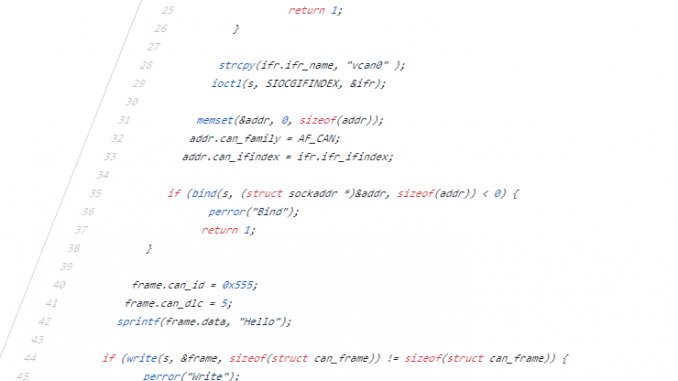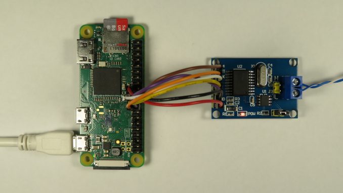
CAN - Controller Area Network
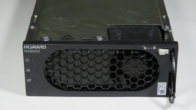
Review: Huawei R4850G2 Power Supply 53.5VDC, 3kW with CAN
The Huawei R4850G2 is a very capable 48V Telecommunications grade power supply available brand-new at cheap surplus prices (normally under $100 USD). Rated at 3000W, it can deliver a considerable 56.1A when powered from a suitable 200-240V rated AC source. The CAN2.0B interface allows for online monitoring and/or adjustment of …