

Anyone who has used a USB Type-A plug will know the fact that it takes three attempts to successfully insert.
The USB Type-C connector sets out to solve this life’s little annoyance. But it doesn’t just stop there, it also offers many other advantages:
- Reversible plug.
- No upstream/downstream facing connector. The cable now has the same connector on both ends.
- Smaller connector allowing for thinner devices such as phones and tablets.
- Higher bandwidth from Super Speed differential pairs.
- Configuration Channel (CC).
- Increased power delivery (up to 100W).
- Non-USB signalling such as Display Port (Alternate mode) and Analog Audio (Accessory mode).
- And all while still being backwards compatible with older USB versions.
Power Delivery
USB has established itself as an industry standard for low voltage (5V) power and charging. Today everything from mobile phones, portable speakers to bike lights have a USB port for charging.
USB ports can now be found integrated into power points, in cars, at bus shelters and even on trains. It’s been a big positive for e-waste, reducing the number of different wall warts required for our insatiable appetite for technology.
USB Power Delivery hopes to expand this experience to more power-hungry devices such as laptop computers. With USB Power Delivery, devices can now request power up to 100W (20V @ 5A).
USB Type-C Receptacle Pinout
The Type-C Receptacle has the following pins:
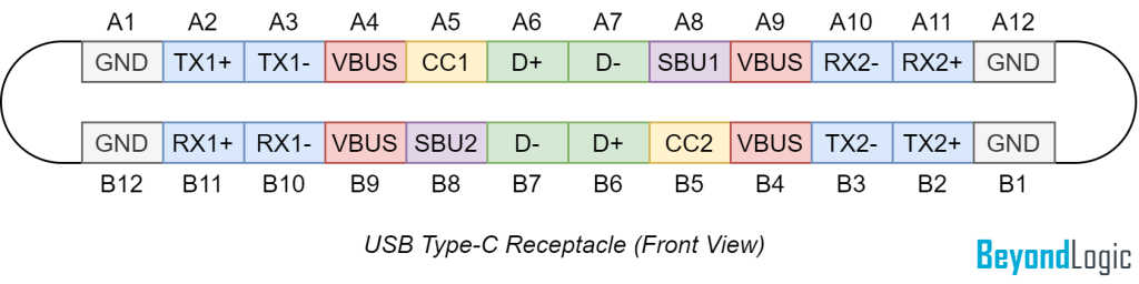
- SuperSpeed differential pairs TX1, RX1, TX2, RX2 (known as SSTX and SSRX in releases prior to 2.0) can be used for SuperSpeedUSB/USB4 signalling. Using the two lanes, USB4 can achieve speeds of 40Gbps.
- But don’t be scared off by signal integrity constraints and increased costs of SuperSpeed: D+/D- is our backwards compatible, slower, old school USB 2.0 pair ready for your MCU or USB to UART converter.
- VBUS – Main bus supply; can be between 5 and 20V and supply up to 100W with a suitable power contract.
- CC1/CC2 – Configuration Channel.
- SBU1/SBU2 – Sideband Use pins e.g. Analog Audio. (For USB4, these signals are used for SBTX and SBRX)
USB Type-C Plug Pinout
The Type-C plug has the following pins:
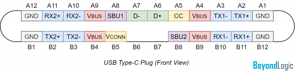
The first thing you will notice is the absence of pins B6/B7 on the plug.
But, if you are really observant, you will notice there is only a single CC pin, and a new pin defined called VCONN. (VCONN is a source of 5V power to electronics within an Electronically Marked Cable Assembly EMCA).
At the heart of the connector is the configuration channel (CC) – used to determine plug orientation, communications device roles, power capabilities and alternative signalling.
As the plug can be inserted right-side-up or upside-down (flipped) CC1 on the receptacle will align with either CC or VCONN of the cable. CC2 will align with the alternate pin.
While the connector and cable no longer defines a physical upstream/downstream connection, USB still preserves the logical host-to-device relationship.
The initial power configuration can be defined as:
- Source – port exclusively acts as a supply of power.
- Sink – port exclusively consumes power.
- Dual Role Power (DRP) – port can either supply or consume power.
The following definitions are used if the device also supports data transfer:
- Downstream Facing Port (DFP).
- Upstream Facing Port (UFP).
- Dual Role Data (DRD).
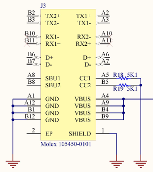
Sink
Attachment of a sink is detected with CC being connected/pulled down to GND. Rd is defined as 5.1 kΩ. As the cable can be flipped, two Rd pull down resistors are required, one for CC1 and the other for CC2.
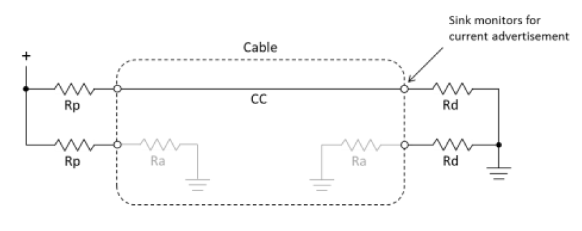
Ra is defined as 800Ω to 1.2kΩ, however as this line (VCONN) is used to power active devices, the standard makes clear it could actually be less if powering active circuitry.
A Sink device will look like:
According to the USB-C specification, power to VBUS should not be applied until a Sink device is detected. Hence if the 5.1 kΩ are omitted, it is possible your device will not receive VBUS power. (Due to backwards compatibility, this is not always the case. For example, a Type-A to USB-C cable is likely to always provide 5V VBUS power).
Source
The source consists of a resistor (Rp) pulled up to 3.3 or 5 V, or a constant current source.
USB Type-C Current
By default, USB 2.0 provides a default current of 500mA, USB 3.2 single lane provides 900mA and USB 3.2 dual lane – 1500mA.
USB Type-C Current advertisements provide a simple mechanism for requesting power exceeding the default USB power provisions.
The Source can advertise Type-C Current by adjusting Rp (or the source current) according to the following table. The Sink can determine the value by reading the voltage present on the CC pin.
| Current Source (1.7 to 5.5V) | Pull-up resistor to 5V | Pull-up resistor to 3.3V | |
| Default USB Power | 80 μA | 56 kΩ | 36 kΩ |
| 1.5A @ 5V (7.5W) | 180 μA | 22 kΩ | 12 kΩ |
| 3.0A @ 5V (15W) | 330 μA | 10 kΩ | 4.7 kΩ |
Multiplexing
As the connector can be flipped, both USB 2.0 pairs (A6/A7 & B6/B7) need to be connected at the Receptacle. At USB 2.0 speeds stubs are acceptable and this helps reduce complexity and save cost.
However for the higher speed pairs, it is not as simple. In the cable, differential pair TX1 is connected to RX1 and TX2 is connected to RX2.
If the end user connects both sides of the cable right-side-up, then the transmitter will always drive the correct receiver pair. However, if they flip one side, then lane 1 will be driving line 2 and vice versa.
Therefore the device should detect the orientation of the plug via the CC pin and using a multiplexer, establish proper routing between the lanes.
USB Power Delivery (PD)
Negotiating power up to 100 watts can be performed using USB Power Delivery. USB Power Delivery contracts are negotiated over the CC pin using Biphase Mark Coding (BMC) at 300kBaud +/-10%, half duplex.
Be the first to comment